
 English
 Español
 عربى
عربى русский
 中文简体
中文简体
The fundamental difference between ERW and EFW steel pipes lies in the welding mechanism: ERW (Electric Resistance Welded) pipes use electrical resistance to heat the strip edges and apply mechanical pressure to forge a bond without filler metal, while EFW (Electric Fusion Welded) pipes employ an electric arc to melt both the base material and a consumable filler metal, creating a fusion bond. This single distinction cascades into differences in weld seam integrity, pressure handling capacity, applicable pipe sizes, and suitable service environments.
Content
- 1 What Is ERW Pipe? Definition and Manufacturing Process
- 2 What Is EFW Pipe? Definition and Fusion Welding Process
- 3 Core Differences Between ERW and EFW: A Detailed Comparison
- 4 Application Scenarios: Where Each Pipe Type Excels
- 5 Quality Assurance and Non-Destructive Testing Requirements
- 6 Material Grades and Steel Chemistry Considerations
- 7 Environmental and Sustainability Factors
- 8 Decision Framework: How to Choose Between ERW and EFW
- 9 Manufacturing Standards and Specifications at a Glance
- 10 Frequently Asked Questions About ERW and EFW Pipe
- 11 Future Trends: Automation and Digital Inspection
- 12 Conclusion
What Is ERW Pipe? Definition and Manufacturing Process
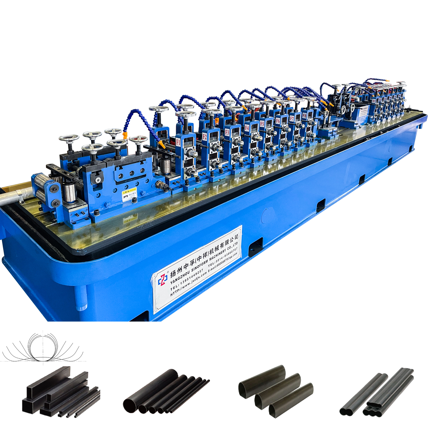
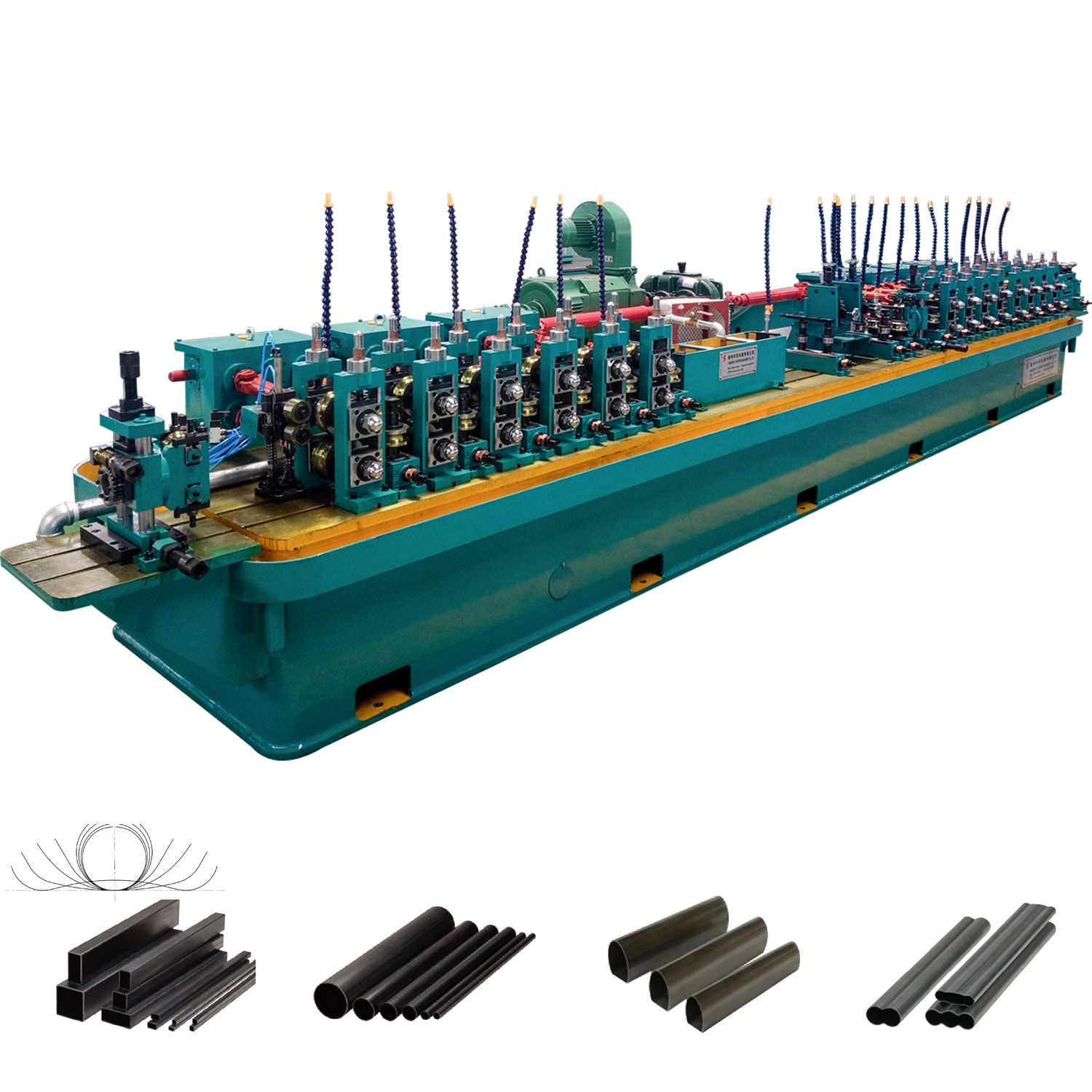
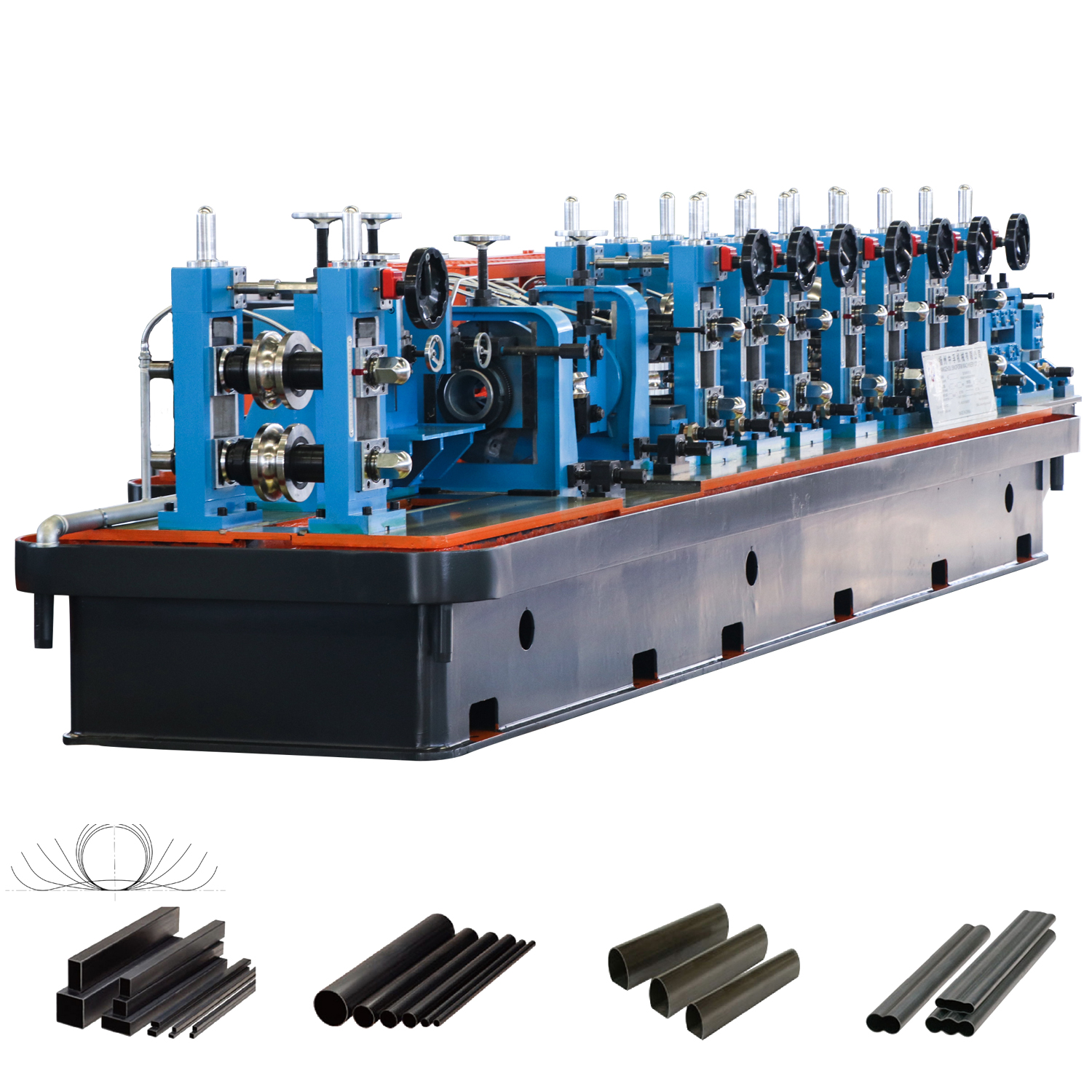
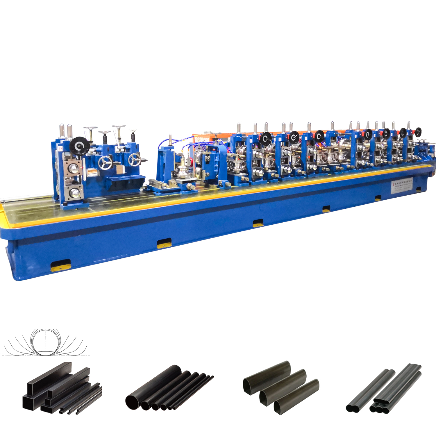
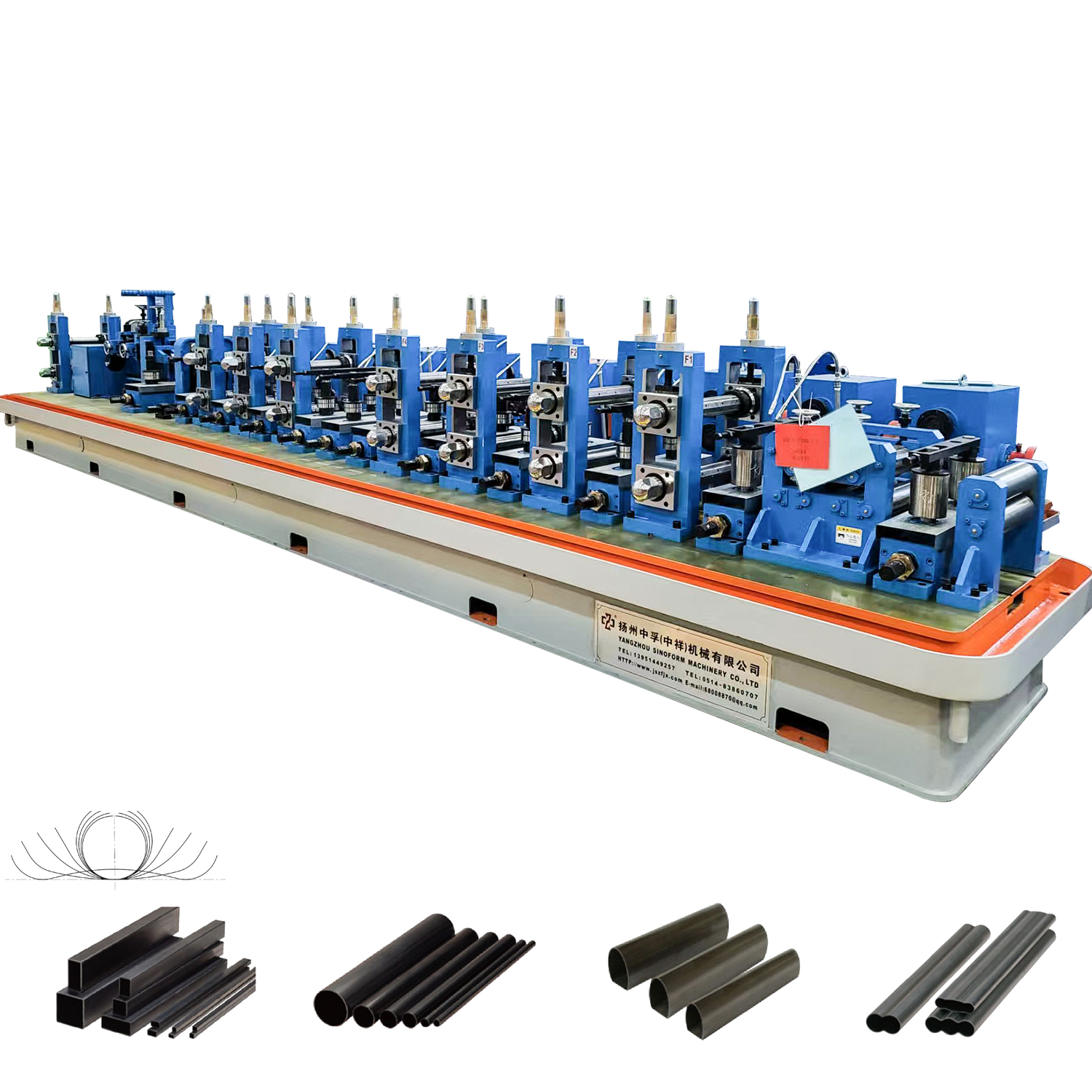
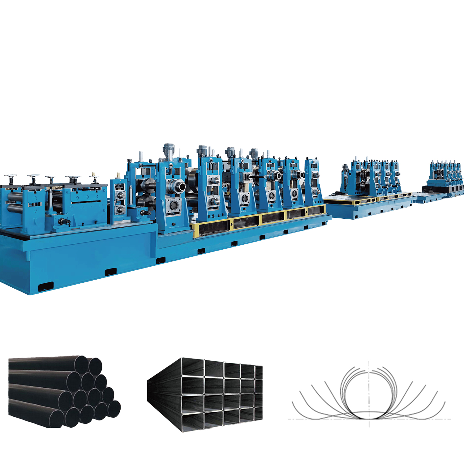
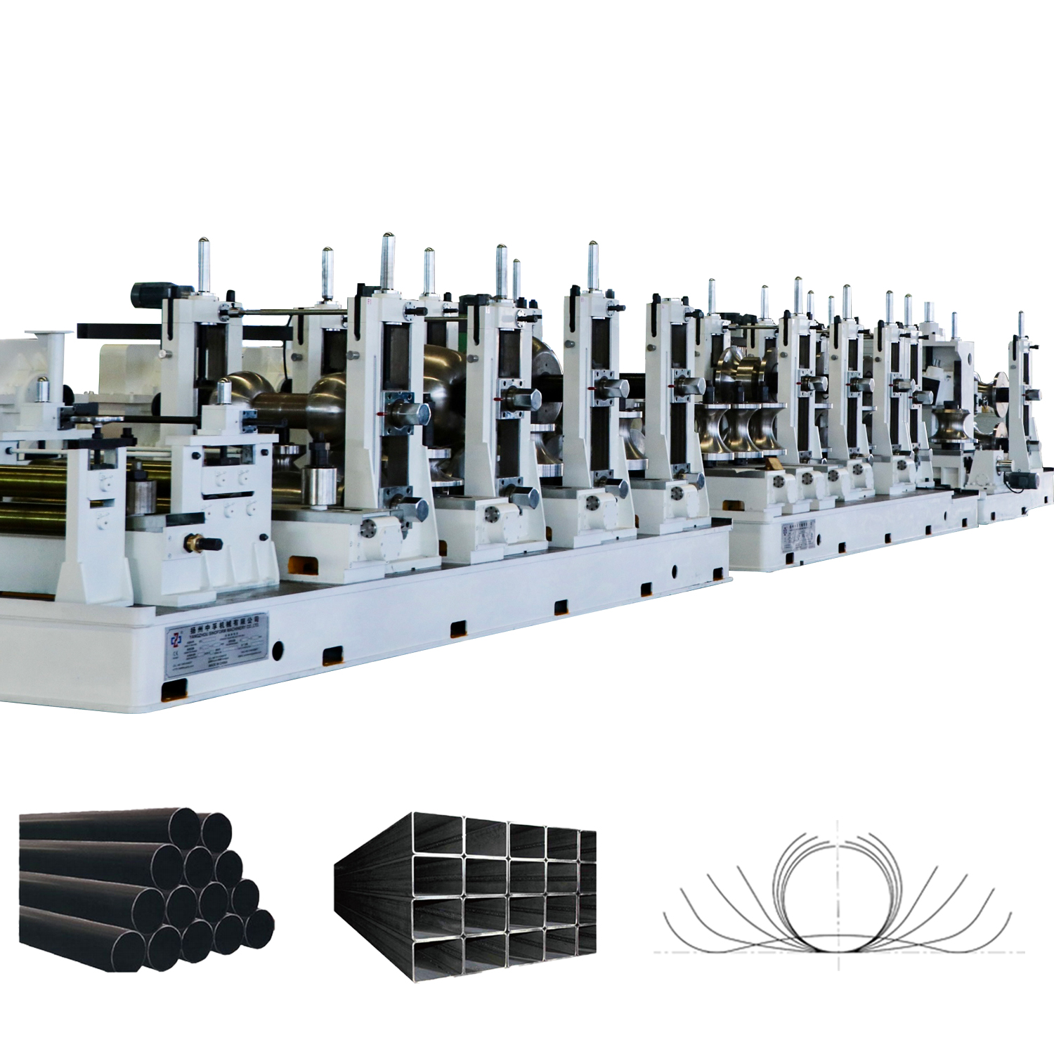
ERW (Electric Resistance Welded) pipe is a longitudinally welded tubular product manufactured from hot-rolled steel coil strip, where the welding is achieved without the addition of any filler material. The process relies entirely on the base metal’s own material to form the bond. According to data from the American Petroleum Institute, ERW pipes account for a significant portion of line pipe used in oil and gas transmission, particularly in diameters up to 24 inches. The production process begins with a flat steel strip that passes through a series of forming rollers, gradually shaping it into a cylindrical tube. As the edges converge, a set of copper electrode wheels or induction coils applies a high-frequency alternating current—typically ranging from 100 kHz to 800 kHz. This current concentrates on the strip edges, raising the temperature rapidly to the forging range (approximately 1300 to 1450 degrees Celsius). Immediately after heating, squeeze rollers apply controlled mechanical pressure, typically between 30 and 70 MPa, to upset the molten edges and expel any oxides or impurities. The result is a solid-phase bond characterized by a narrow heat-affected zone and a fine grain structure.
A critical quality indicator for ERW pipe is the presence of a visible internal and external weld flash—the excess material squeezed out during forging. This flash is normally trimmed away. In the early decades of ERW production, low-frequency current (60 to 360 Hz) was common, which sometimes led to incomplete fusion and contact marks. However, modern high-frequency ERW technology, combined with in-line ultrasonic testing and post-weld heat treatment of the seam, has dramatically improved reliability. A 2018 review published in the Journal of Materials Processing Technology noted that properly manufactured high-frequency ERW pipes now exhibit toughness values at the weld zone that match or exceed the base metal, even at low service temperatures down to minus 45 degrees Celsius.
Key Advantages of ERW
- High production speed—modern mills produce up to 100 meters per minute on small diameters
- Excellent dimensional accuracy and concentricity due to cold forming from precise strip
- No filler metal means a homogeneous chemistry across the entire pipe circumference
- Cost-effective for thin to medium wall thicknesses up to approximately 16 mm
- Widely available in standard sizes from 1/2 inch to 24 inches nominal diameter
Common Limitations
- Limited to longitudinal seam only—no spiral option available
- Wall thickness is constrained by strip availability and forming forces
- Risk of groove corrosion at the weld line if not properly heat-treated
- Not suitable for extremely thick-walled pressure vessels exceeding 20 mm wall
What Is EFW Pipe? Definition and Fusion Welding Process
EFW (Electric Fusion Welded) pipe is manufactured using an electric arc that melts both the base steel plate edges and a consumable filler electrode, producing a fusion bond with a cast weld metal structure. Unlike ERW, the EFW process intentionally introduces additional material into the weld joint, which can be tailored for specific mechanical properties or corrosion resistance. The term EFW broadly encompasses several arc welding techniques, most notably Submerged Arc Welding (SAW)—which itself splits into longitudinal (LSAW) and spiral (SSAW/HSAW) variants—as well as gas-shielded processes. In a typical EFW pipe mill, a flat steel plate is first edge-prepared with a bevel or J-groove profile. The plate is then formed into a cylinder using a press brake, Uing press, Oing press, or a three-roll bending machine. The longitudinal joint is tack-welded and then subjected to a multi-pass submerged arc welding procedure. A single wire or tandem wire system deposits filler metal under a blanket of granular flux, which shields the arc, stabilizes it, and shapes the weld bead. Welding currents in EFW operations range from 400 to over 1200 amperes, with deposition rates reaching 8 to 20 kg per hour depending on the number of wires and the diameter of the electrode.
The EFW weld zone is characterized by a cast dendritic microstructure that differs distinctly from the wrought structure of the parent plate. This as-cast weld metal typically exhibits slightly lower toughness than the base material unless carefully controlled. According to a technical paper presented at the 2020 International Pipeline Conference, the Charpy V-notch impact energy of an EFW seam in X70 grade steel measured at minus 20 degrees Celsius averaged 180 Joules, compared to 250 Joules for the base plate—still well above the minimum code requirement of 40 Joules for many standards. Post-weld heat treatment (PWHT) is often applied to EFW pipes intended for sour service or low-temperature applications to temper the martensitic regions and relieve residual stresses that can exceed 300 MPa in the as-welded condition.
Core Differences Between ERW and EFW: A Detailed Comparison
The distinction between these two welded pipe categories extends far beyond the simple presence or absence of filler metal. A systematic comparison across multiple technical dimensions reveals where each technology excels and where it falls short, enabling engineers and procurement specialists to make data-driven decisions.
1. Welding Mechanism and Metallurgical Bond
The weld in an ERW pipe is formed by solid-state bonding under pressure after localized resistance heating. There is no melting of the bulk material under ideal conditions—the edges reach a mushy forging state and are squeezed together, expelling surface oxides. This creates a bond line that is essentially a recrystallized grain boundary with minimal chemical segregation. In contrast, the EFW seam undergoes full melting and resolidification. The filler metal mixes with the melted base metal edges in a weld pool, and upon cooling, forms a cast structure with possible columnar grain growth, microsegregation of alloying elements, and non-metallic inclusions originating from the flux. An API 5L line pipe specification allows both types, but supplementary requirements for weld toughness testing are more common for EFW pipe due to this inherent microstructural difference.
2. Applicable Diameter and Wall Thickness Ranges
ERW pipes are commercially produced in outer diameters from 21.3 mm (1/2 inch) up to approximately 610 mm (24 inches), with wall thicknesses ranging from 1.5 mm to 16 mm, and in some specialized mills up to 20 mm. The upper limit is dictated by the capacity of forming rolls and the available strip width. EFW pipes, by comparison, cover a much broader and thicker range. Longitudinal EFW (LSAW) pipes are commonly produced from 406 mm (16 inches) up to 1626 mm (64 inches) in diameter, with wall thicknesses from 6 mm to 65 mm. Spiral EFW (SSAW) pipes can reach diameters exceeding 2500 mm. Data from the International Tube Association indicates that for wall thicknesses above 25 mm, EFW is the only commercially viable longitudinally welded option.
3. Pressure Rating and Mechanical Reliability
The joint efficiency factor—a multiplier applied to the base material's allowable stress in pressure design—differs between the two pipe types. ERW pipes manufactured to API 5L or ASTM A53 standards typically carry a joint efficiency factor of 0.85 to 1.0, depending on the extent of non-destructive examination. The seamless-like nature of a well-made ERW seam can achieve a factor of 1.0 when ultrasonically tested over the full length. EFW pipes under ASME B31.3 process piping code are assigned a joint efficiency of 0.95 for single-welded seams with spot radiography and 1.0 for double-welded seams with full radiography. In practice, a 12-inch Schedule 80 ERW pipe in Grade X52 might be rated for a maximum allowable working pressure of 13.8 MPa at ambient temperature, while an equivalent EFW pipe with the same dimensions and a double-welded seam could be rated for 14.5 MPa due to the slightly higher wall thickness tolerance achievable in plate forming.
4. Cost Structure and Production Economics
For small to medium diameters with thin to moderate walls, ERW offers a significant cost advantage. A market survey conducted in mid-2025 across Asian and Middle Eastern mills showed that the ex-works price per ton for 8-inch Schedule 40 API 5L Grade B ERW pipe averaged 720 to 850 US dollars, while an equivalent EFW pipe ranged from 960 to 1150 US dollars—a premium of roughly 25 to 35 percent. This gap narrows as diameter increases. For 36-inch pipe with 12 mm wall thickness, the EFW option becomes price-competitive because ERW mills simply cannot produce that size. The higher cost of EFW stems from slower production speeds (typically 1.5 to 4 meters per minute for longitudinal SAW versus up to 60 meters per minute for small-bore ERW), greater energy consumption, the cost of welding consumables and flux, and more extensive post-weld inspection requirements.
5. Corrosion Behavior at the Weld Seam
The galvanic potential difference between the weld zone and the base metal can drive preferential corrosion. In ERW pipes, the weld zone chemistry is essentially identical to the base metal, which minimizes macro-galvanic cell formation. However, if the post-weld heat treatment is inadequate, the slightly harder and more stressed microstructure at the fusion line can become anodic in certain electrolytes, leading to localized groove corrosion. This phenomenon has been documented in water injection pipelines in the Middle East, where groove corrosion rates of 0.3 to 0.7 mm per year were observed at ERW seams that had not received normalizing heat treatment. EFW pipes, with their dissimilar weld metal chemistry, can exhibit preferential weld corrosion if the filler metal is not correctly matched. In sour service environments containing hydrogen sulfide, the hardness of the as-deposited EFW weld metal—which can exceed 250 HV without PWHT—increases susceptibility to sulfide stress cracking. NACE MR0175 imposes a maximum hardness of 250 HV and often requires PWHT for EFW pipe welds in sour service.
| Feature | ERW Pipe | EFW Pipe |
|---|---|---|
| Welding Type | Resistance / Pressure Forge | Arc Fusion with Filler Metal |
| Filler Metal Required | No | Yes (consumable electrode/wire) |
| Weld Seam Type | Longitudinal only | Longitudinal (LSAW) or Spiral (SSAW) |
| Typical Diameter Range | 1/2 inch to 24 inches | 16 inches to 64+ inches |
| Wall Thickness Capacity | 1.5 mm to 20 mm | 6 mm to 65 mm |
| Weld Joint Efficiency | 0.85 to 1.0 (code dependent) | 0.95 to 1.0 (with full radiography) |
| Production Speed | High (up to 100 m/min on small OD) | Low to moderate (1 to 4 m/min LSAW) |
| Raw Material Form | Hot-rolled coil / strip | Steel plate |
| Relative Cost (small dia.) | Lower base cost | 25 to 35% premium |
| Typical Standards | API 5L, ASTM A53, ASTM A135 | API 5L, ASTM A671, ASTM A672 |
| Heat-Affected Zone | Narrow (1 to 3 mm) | Wider (3 to 8 mm multi-pass) |
Comparison of key technical and economic parameters between ERW and EFW steel pipes based on typical industry practice and API 5L / ASTM standard requirements.
Application Scenarios: Where Each Pipe Type Excels
Selecting between ERW and EFW pipes is rarely a purely technical decision—it is driven by the specific demands of the service environment, project economics, and regulatory requirements. Mapping typical applications clarifies the practical dividing line.
ERW Dominant Applications
- Low to medium pressure gas distribution networks (up to 7 MPa operating pressure)
- Water and wastewater transmission mains
- Structural hollow sections for building and bridge construction
- Automotive exhaust and fluid transfer tubing
- Oil country tubular goods (casing and tubing) up to API 5CT Grade N80
- Fire protection sprinkler systems per NFPA 13
- Scaffolding and mechanical engineering tubular components
EFW Dominant Applications
- High-pressure cross-country oil and gas trunk lines (operating at 10 to 15 MPa)
- Large-diameter penstocks for hydroelectric power plants
- Pressure vessels and boiler shells per ASME Section VIII
- Offshore platform risers and subsea flowlines in deep water
- Sour service pipelines requiring PWHT per NACE MR0175
- Piling and structural supports for marine terminals and jetties
- Nuclear power plant cooling water intake and discharge lines
Quality Assurance and Non-Destructive Testing Requirements
Both ERW and EFW pipe specifications mandate rigorous inspection protocols, but the focus areas differ based on the failure modes inherent to each process. For ERW pipe, the primary concern is the potential for lack-of-fusion defects, stitching (intermittent bonding), and hook cracks at the weld line. Consequently, API 5L requires 100 percent ultrasonic inspection of the ERW weld seam over its entire length, typically using shear wave probes angled at 45 and 60 degrees to detect planar defects. Eddy current testing may also be applied for surface-breaking imperfections. For EFW pipe, the defects of concern include slag inclusions, porosity, incomplete penetration at the root, and transverse cracks. Radiographic testing (RT) using X-ray or gamma-ray sources remains the dominant volumetric inspection method for EFW seams, often supplemented by ultrasonic testing for thick-walled joints. According to a 2023 industry survey by the Pipeline Research Council International, the defect detection probability for a 3 mm lack-of-fusion flaw in a 15 mm wall pipe reaches approximately 92 percent with modern phased-array ultrasonic testing for ERW seams and about 88 percent with digital radiography for EFW seams.
Material Grades and Steel Chemistry Considerations
ERW pipes are typically produced from low-carbon or micro-alloyed steels with carbon equivalents (CE) below 0.40 to ensure good weldability in the solid state. Common grades include API 5L Grade B (yield strength 241 MPa minimum), X42 (290 MPa), X52 (359 MPa), and up to X70 (483 MPa) in advanced high-frequency mills. The carbon equivalent formula CE(IIW) = C + Mn/6 + (Cr+Mo+V)/5 + (Ni+Cu)/15 is strictly controlled because excessive hardenability can produce brittle martensitic bands at the ERW fusion line during rapid post-weld cooling. EFW pipes can accommodate a wider range of steel grades, including high-strength low-alloy (HSLA) steels up to X80 and X100, as well as alloy steels such as ASTM A387 Grade 11 and 22 for elevated temperature service. The welding consumables for EFW are selected to slightly overmatch the base metal tensile strength by 10 to 20 percent, and to maintain adequate toughness at the minimum design metal temperature. For a typical X65 EFW line pipe project in the North Sea, the specified filler wire chemistry included 0.08 percent carbon, 1.5 percent manganese, 0.35 percent silicon, and 0.6 percent nickel to achieve a weld metal yield strength above 480 MPa with Charpy toughness exceeding 60 Joules at minus 40 degrees Celsius.
Environmental and Sustainability Factors
The carbon footprint of pipe manufacturing has gained attention in the context of global emissions reduction targets. ERW production is inherently more energy-efficient per ton of finished pipe. A life-cycle assessment published by the World Steel Association in 2022 estimated that producing one metric ton of small-diameter ERW pipe emits approximately 0.8 to 1.1 metric tons of CO2 equivalent, encompassing steelmaking, hot rolling, and pipe forming. The comparable figure for heavy-wall EFW pipe ranges from 1.3 to 1.7 metric tons of CO2 equivalent, reflecting the additional plate rolling steps, the energy-intensive welding process, and the common requirement for post-weld heat treatment in a gas-fired furnace. However, the longer service life and higher reliability of EFW pipes in critical applications can offset this initial carbon penalty over a 50-year design life. A 2024 study in the Journal of Cleaner Production modeled a 200-kilometer, 36-inch gas transmission pipeline and found that while the EFW option had a 22 percent higher embodied carbon at construction, the reduced leakage risk and lower maintenance intervention resulted in a 9 percent lower total life-cycle carbon footprint compared to a hypothetical scenario using smaller-diameter ERW pipes with more field girth welds.
Decision Framework: How to Choose Between ERW and EFW
The selection process can be distilled into a logical sequence of considerations. Project engineers should systematically evaluate the following factors, weighted by the specific context of the application.
Step-by-Step Selection Guide
- Determine the required diameter and wall thickness. If the outer diameter exceeds 24 inches or the wall thickness exceeds 20 mm, EFW is practically the only available option. For diameters below 8 inches with standard wall schedules, ERW is generally more economical.
- Assess the design pressure and temperature. Refer to ASME B31.3 or B31.4 to calculate the required wall thickness. Compare the joint efficiency factors for each pipe type under your inspection scope. For pressures exceeding 10 MPa in large diameters, EFW with full radiography offers higher confidence.
- Evaluate the fluid corrosivity. For sweet (non-sour) hydrocarbon service, both types are suitable with proper chemistry control. For sour service per NACE MR0175, specify the required hardness testing and PWHT—more readily achieved with EFW pipe due to the controlled thermal cycle.
- Consider the total installed cost. Account not only for the pipe mill price but also for transportation, field welding productivity, and the number of girth welds. Larger EFW pipes reduce the total number of field joints, which can lower overall project cost despite higher material unit price.
- Check availability and lead time. ERW pipe in standard sizes is typically available from stock or with short lead times of 4 to 8 weeks. Large-diameter EFW pipe is often made to order with lead times of 12 to 20 weeks, especially for alloy or high-strength grades.
- Verify code acceptance. Some owners and jurisdictions have specific preferences. For instance, certain offshore operators require double-submerged-arc welded (EFW) pipe for all riser applications regardless of diameter.
Manufacturing Standards and Specifications at a Glance
A clear understanding of the governing standards helps procurement teams specify the correct product and avoid costly misunderstandings. Below is a consolidated reference of the most frequently invoked standards for both pipe types.
| Standard | Pipe Type Covered | Typical Use Case |
|---|---|---|
| API 5L | Both ERW and EFW | Oil and gas line pipe for onshore and offshore |
| ASTM A53 | ERW (Type E) | General structural and pressure applications |
| ASTM A135 | ERW | Fire protection and low-pressure systems |
| ASTM A671 | EFW (fusion welded pipe from plate) | Atmospheric and lower temperature service |
| ASTM A672 | EFW (fusion welded pipe from plate) | Moderate and high-temperature pressure service |
| ASME B36.10 | Both types | Standard dimensions for welded pipe (sizes and schedules) |
Summary of principal international standards governing ERW and EFW steel pipe manufacturing, inspection, and dimensional requirements.
Frequently Asked Questions About ERW and EFW Pipe
Can ERW pipe be used for high-pressure gas transmission?
Yes, provided the diameter and wall thickness are within the mill's capability and the seam is 100 percent ultrasonically tested. Many cross-country gas pipelines operating at pressures up to 10 MPa use ERW pipe in diameters up to 24 inches. However, for larger diameters and higher pressures, EFW (LSAW) is the conventional choice due to its higher joint efficiency under full radiography and the ability to use thicker walls.
What does the term ERW pipe full form stand for?
The full form of ERW is Electric Resistance Welded, reflecting the process where electrical resistance heats the steel strip edges to forging temperature, followed by mechanical pressure to create a solid-state bond without any filler metal addition.
Why is EFW pipe preferred for sour service?
The EFW process allows precise control over weld metal chemistry through filler selection and offers a well-established post-weld heat treatment path to reduce hardness below the 250 HV threshold required by NACE MR0175. While ERW pipe can also be used in sour service with proper seam normalizing, the historically documented cases of preferential seam corrosion in older low-frequency ERW pipe have made some operators more conservative, favoring EFW for critical sour gas applications.
Is ERW pipe seamless?
No. ERW pipe has a longitudinal weld seam, albeit one that is metallurgically very similar to the base metal and essentially invisible after proper trimming and heat treatment. It should not be confused with seamless pipe, which is formed by piercing a solid billet and has no weld seam at all. The distinction matters for certain code calculations where a seamless pipe may carry a higher allowable stress than a welded pipe of the same grade.
How can I visually distinguish an ERW weld from an EFW weld?
On the external surface of an ERW pipe, the weld seam is typically flush or has a very faint, narrow line where the flash was trimmed. The internal surface may show a slightly raised bead if trimming was incomplete. An EFW weld, particularly a submerged-arc weld, exhibits a wider, slightly raised reinforcement bead—often 2 to 4 mm in height and 10 to 20 mm in width—with a rippled surface texture characteristic of the solidifying slag. Inside the pipe, the root pass of a double-welded EFW joint usually shows a similar raised profile.
Future Trends: Automation and Digital Inspection
Both ERW and EFW manufacturing are being transformed by Industry 4.0 technologies. In high-frequency ERW mills, infrared cameras now monitor the heat signature at the strip edges in real time, with closed-loop feedback adjusting the welding current within milliseconds to compensate for variations in strip thickness or chemistry. Artificial intelligence algorithms trained on thousands of ultrasonic inspection records can predict the probability of a weld defect before it occurs, allowing operators to adjust squeeze pressure or line speed proactively. In EFW production, robotic multi-wire submerged arc welding stations with seam-tracking lasers achieve deposition rates exceeding 25 kg per hour with defect rates below 0.2 percent. The convergence of these technologies is gradually narrowing the historical quality gap between the two pipe types, making ERW pipe increasingly competitive in domains once dominated by EFW.
Conclusion
The choice between ERW and EFW pipe is fundamentally a function of size, pressure, service environment, and project economics. ERW delivers a cost-optimized, high-productivity solution for diameters up to 24 inches with thin to moderate walls, leveraging a solid-state forge bond that closely mimics the base metal properties when properly heat-treated. EFW extends the envelope into large diameters and heavy walls, offering the versatility of arc welding with filler metal, multi-pass capability, and proven performance in the most demanding high-pressure and sour service applications. Neither type is universally superior; each occupies a well-defined niche in the vast landscape of steel pipe technology. Understanding the specific demands of the project—and matching them to the strengths of each welding process—remains the engineer's most reliable guide.