
 English
 Español
 عربى
عربى русский
 中文简体
中文简体
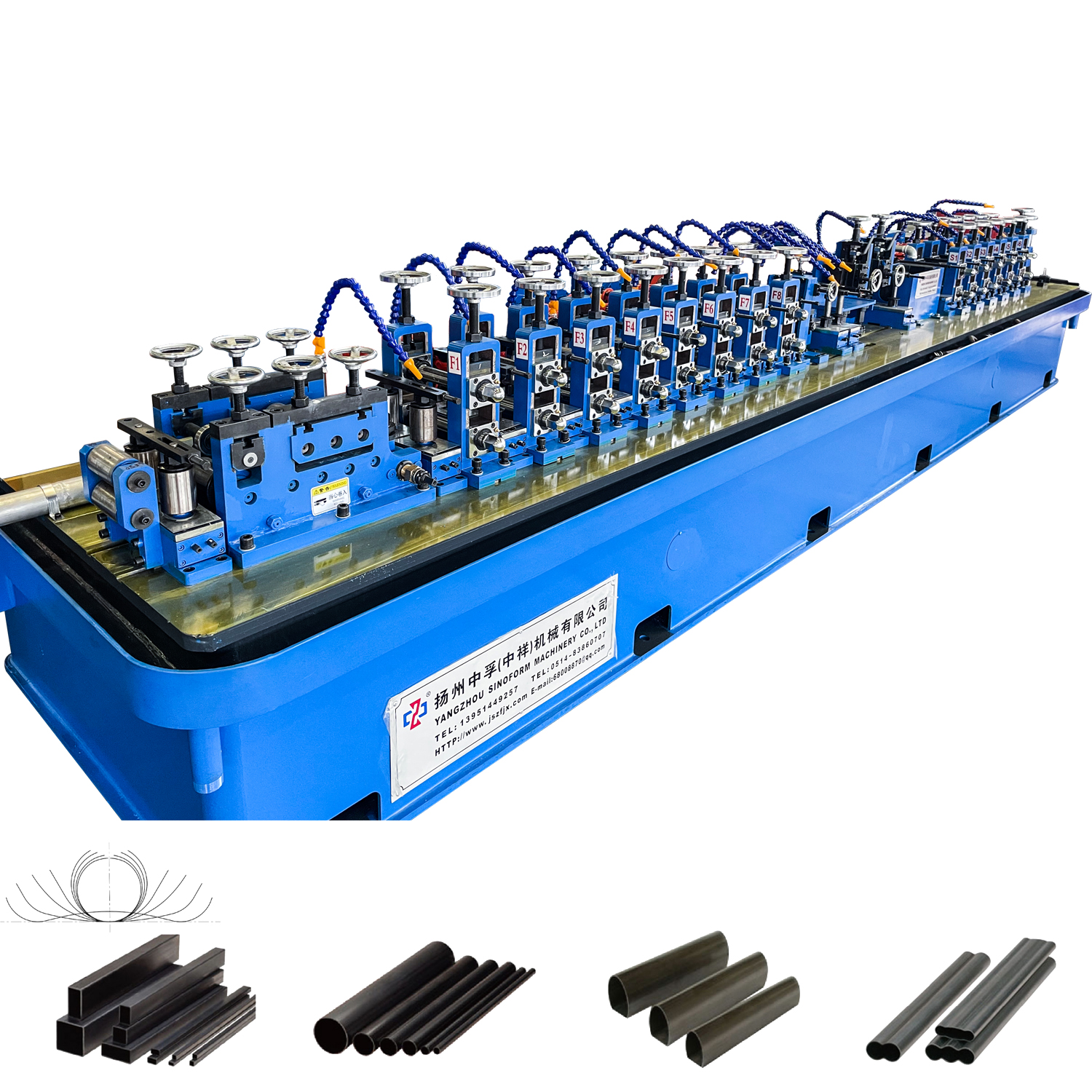
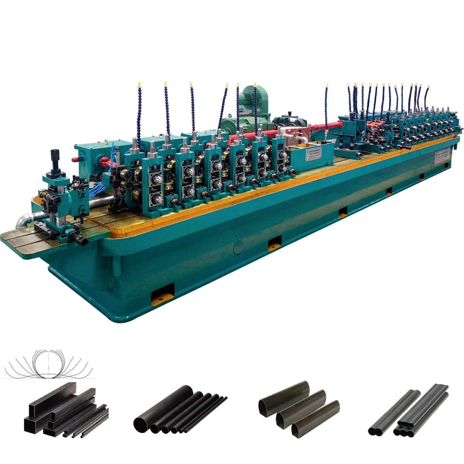
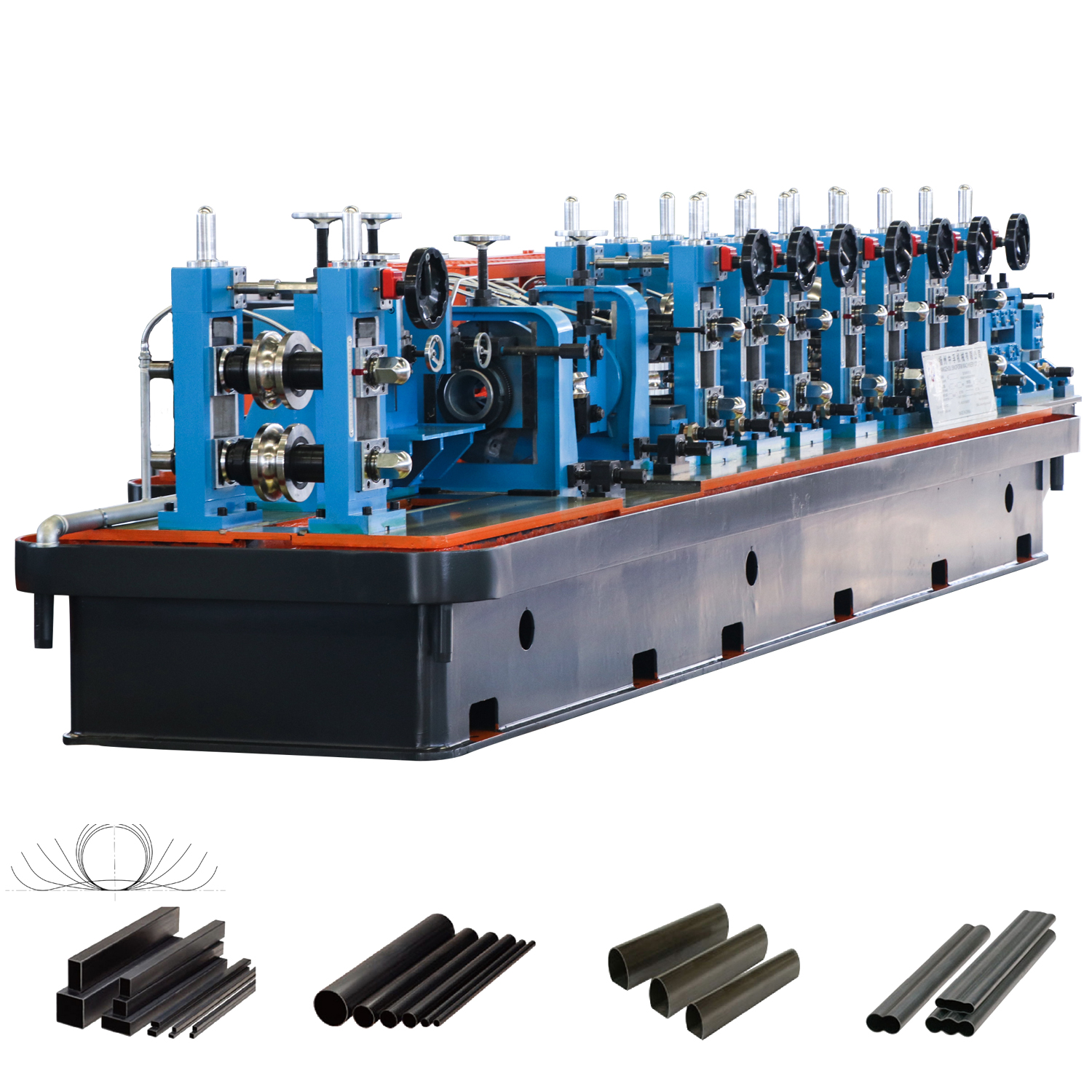
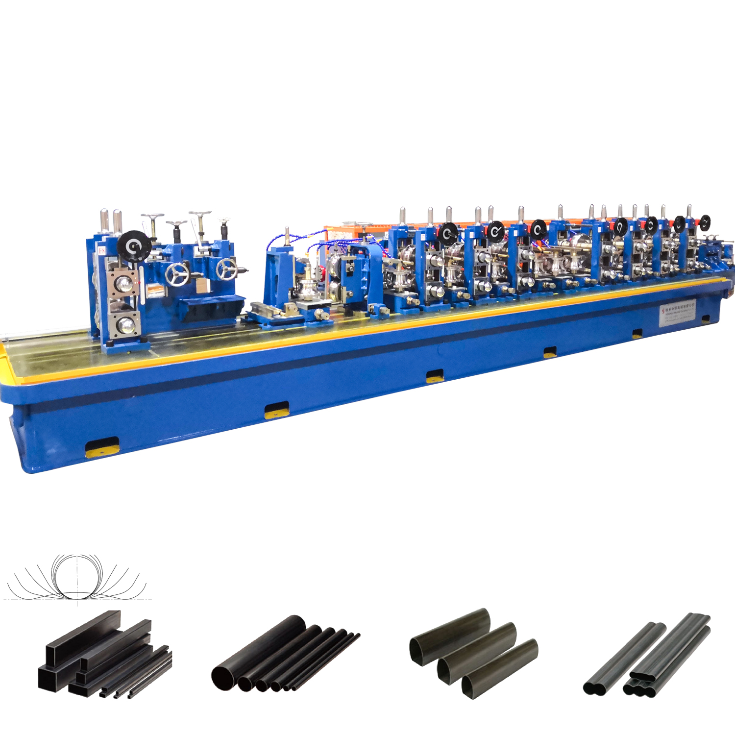
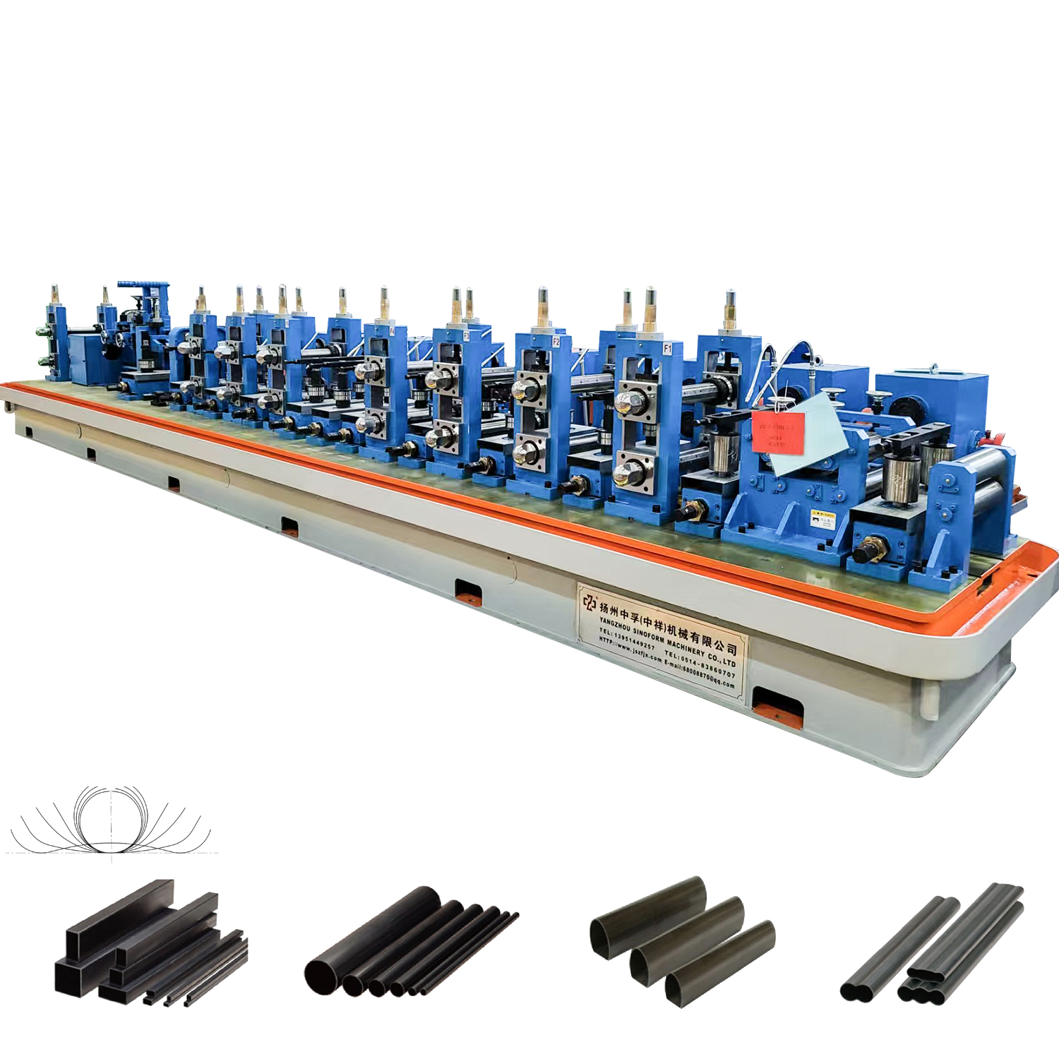
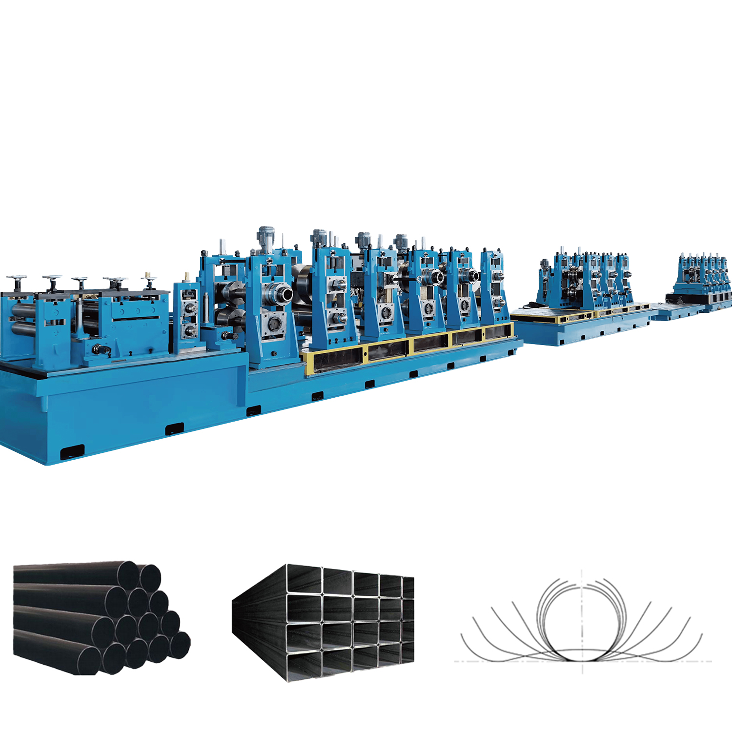
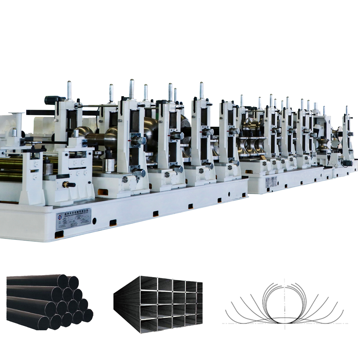
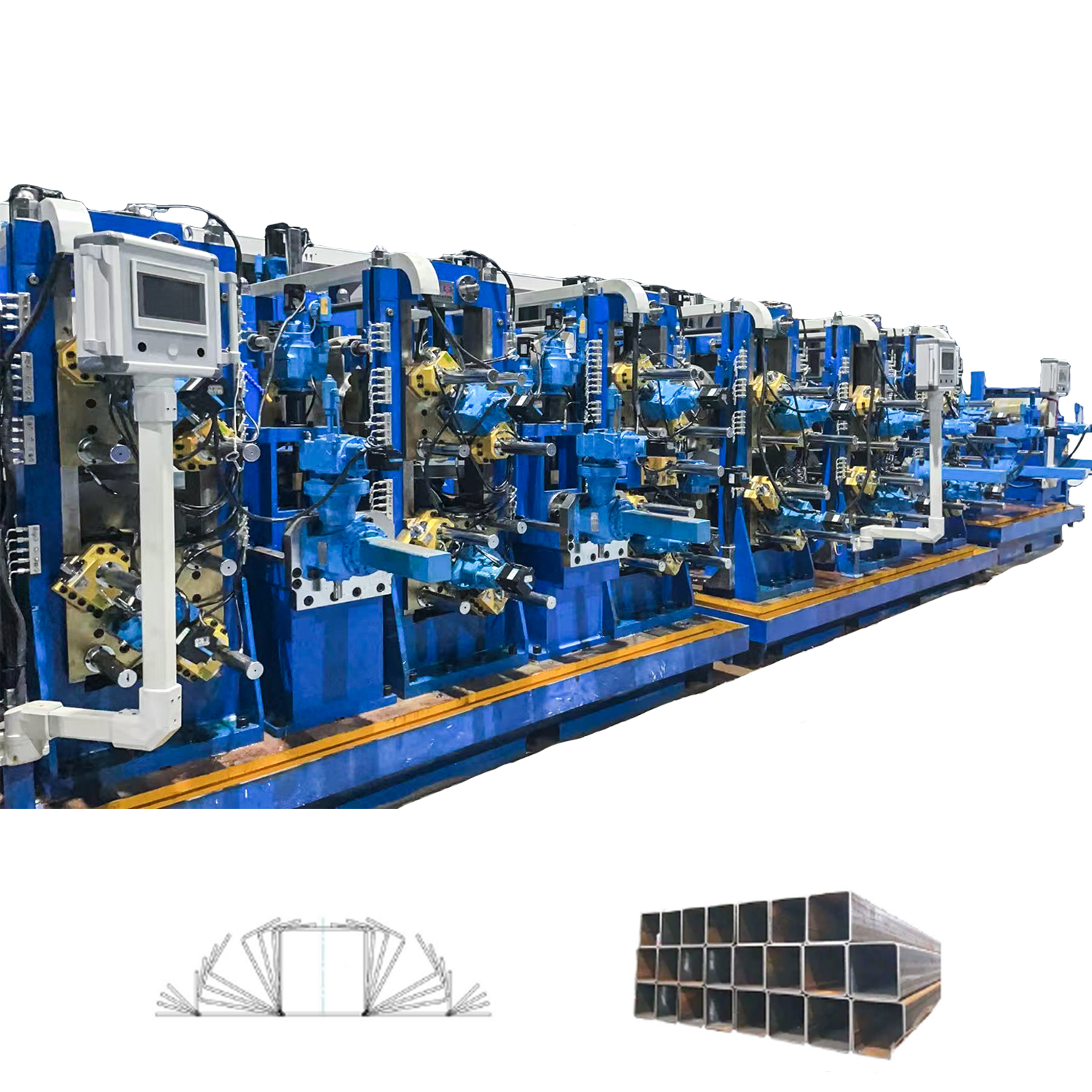
A high frequency tube mill machine is a continuous roll-forming and welding production line that shapes flat steel strip into round, square, or rectangular tubes by progressively bending the strip through a series of forming rollers and then fusing the open seam using high-frequency electrical resistance or induction welding — producing finished welded steel tube at speeds of 10 to 120 meters per minute depending on the model and material. It is the dominant manufacturing technology for structural steel pipes, hollow sections, furniture tubing, automotive components, and precision mechanical tubing worldwide, chosen for its high output speed, narrow heat-affected zone, and consistent weld quality compared to alternative welding methods.
This article explains exactly how a high frequency tube mill machine works at each production stage, what the key specifications mean, how HF tube mills compare to alternative production methods, which industries rely on them, and what to evaluate when selecting a machine for a new production line.
Content
- 1 How a High Frequency Tube Mill Machine Works: Stage by Stage
- 2 Key Specifications of a High Frequency Tube Mill Machine Explained
- 3 High Frequency Tube Mill vs. Alternative Tube Production Methods
- 4 Which Industries Use High Frequency Tube Mill Machines?
- 5 HF Contact Welding vs. HF Induction Welding: Which Should You Choose?
- 6 How to Choose the Right High Frequency Tube Mill Machine for Your Production Line
- 7 Critical Maintenance Areas on a High Frequency Tube Mill Machine
- 8 Frequently Asked Questions: High Frequency Tube Mill Machine
- 8.1 What materials can a high frequency tube mill machine process?
- 8.2 What is the typical production output of a high frequency tube mill machine per shift?
- 8.3 How long does it take to change over a tube mill from one tube size to another?
- 8.4 What is the difference between a solid-state HF generator and a vacuum tube generator?
- 8.5 Can a single high frequency tube mill machine produce both round and square tube?
- 8.6 What international standards apply to tube produced on high frequency tube mill machines?
- 9 Conclusion: Why the High Frequency Tube Mill Machine Dominates Steel Tube Production
How a High Frequency Tube Mill Machine Works: Stage by Stage
A high frequency tube mill machine processes flat steel strip through six sequential production stages — uncoiling, forming, welding, sizing, straightening, and cutting — all integrated into a single continuous production line. Understanding each stage is essential for evaluating machine specifications and diagnosing production problems.
Stage 1: Uncoiling and Strip Feeding
The process begins with a steel strip coil loaded onto a hydraulic uncoiler. The uncoiler holds coils typically weighing between 3 and 20 tonnes depending on the machine capacity, and feeds the strip into the line at a controlled, constant tension. A looping pit or accumulator between the uncoiler and the forming section absorbs the brief interruptions that occur when one coil runs out and a new one is loaded via strip joining — allowing the mill to continue running without stopping the welding section.
Stage 2: Forming — Shaping the Strip into an Open Tube
The flat strip passes through a series of horizontal and vertical roll stands arranged progressively along the mill. Each stand incrementally bends the strip further toward the target tube profile. A typical high frequency tube mill machine uses between 8 and 20 forming roll stands depending on the tube diameter range and wall thickness. The forming section produces an open-seam tube — essentially a cylinder with a narrow longitudinal gap — ready for welding.
Roll tooling is specific to each tube size and must be changed when switching between product dimensions. Quick-change tooling systems on modern machines reduce changeover time from several hours to under 30 minutes, which is a critical factor in facilities producing multiple tube sizes.
Stage 3: High Frequency Welding — Closing the Seam
This is the defining stage of the high frequency tube mill machine. A high-frequency electrical current — operating at frequencies between 200 kHz and 400 kHz in most industrial models — is applied to the strip edges as they converge toward a set of squeeze rolls (also called pressure rolls or weld rolls). The high-frequency current travels along the strip edges by the skin effect, concentrating heat precisely at the seam edges rather than through the full material cross-section.
When the edges reach the forge welding temperature (approximately 1,300 to 1,400 degrees Celsius for carbon steel), the pressure rolls press them together under controlled forging pressure, fusing the two edges into a seamless metallurgical bond without any filler material. The entire heating and fusion process occurs in milliseconds, producing a narrow heat-affected zone (HAZ) typically between 1 and 4 mm wide on either side of the weld line — far narrower than the HAZ produced by arc welding or gas welding methods.
Two HF welding methods are used in tube mills:
- HF contact welding: Current is delivered to the strip edges through sliding copper contacts (also called shoes or contacts). This method is efficient and widely used for carbon steel and stainless steel tube production. Contact wear is a maintenance consideration.
- HF induction welding: Current is induced in the strip edges by an induction coil positioned around the open seam. No physical contact with the strip is made, eliminating contact wear and enabling higher production speeds. Induction welding is preferred for thin-wall tube, small-diameter precision tube, and copper or aluminum tube production.
Stage 4: Weld Bead Removal (Scarfing)
The forge welding process produces a small external bead of extruded metal along the weld seam. A scarfing tool (a carbide or tool-steel blade) removes this bead flush with the tube surface immediately after the weld rolls. On tubes destined for internal-surface-critical applications, an internal scarfing tool removes the corresponding internal bead. Scarf quality directly affects the surface finish of the finished tube and the life of subsequent tooling.
Stage 5: Sizing, Straightening, and Profile Correction
After welding, the tube passes through a sizing section — a series of roll stands that reduce the tube to its precise final outside diameter (OD) and wall thickness tolerance. The sizing section also corrects any minor ovality introduced during forming. For square and rectangular hollow sections (SHS and RHS), additional profiling stands after the sizing section drive the round tube into its final angular form.
A straightening section follows, using offset rolls to remove any residual bow or camber from the tube before it reaches the cutoff station.
Stage 6: Flying Cutoff
The continuous welded tube is cut to the specified length by a flying cutoff saw or die-accelerated cutoff press that travels with the tube at line speed, completing the cut without stopping the mill. Flying cutoff systems maintain dimensional accuracy to within plus or minus 1 mm over the cut length at normal production speeds. After cutting, finished tubes are collected on a run-out table or bundling system.
Key Specifications of a High Frequency Tube Mill Machine Explained
Understanding what each specification number on a high frequency tube mill machine actually means in production terms is essential for matching the machine to your product range and output requirements.
| Specification | Typical Range | What It Determines | Practical Implication |
| Tube OD range | 6mm to 610mm | Product diameter coverage | Defines which product sizes the mill can produce; tooling sets required per size |
| Wall thickness range | 0.5mm to 16mm | Material thickness capability | Thicker walls require higher HF power and slower line speeds |
| HF welder power (kW) | 50kW to 1,500kW | Maximum production speed for given tube size and wall | Higher power = faster speeds; must match tube cross-section and material grade |
| Line speed (m/min) | 10 to 120 m/min | Output rate per shift | Directly calculates tonnes-per-hour production capacity |
| Strip width range | Depends on OD range | Raw material input size | Determines what coil sizes must be purchased from the steel mill |
| Weld frequency (kHz) | 200 to 400 kHz | Heat penetration depth and HAZ width | Higher frequency = narrower HAZ; critical for thin-wall and high-grade materials |
| Number of forming stands | 8 to 20 stands | Forming quality and thickness range | More stands = better forming control for thick-wall and large-OD tube |
Table 1: Key technical specifications of a high frequency tube mill machine with their typical ranges, what each specification controls, and its practical production implication.
High Frequency Tube Mill vs. Alternative Tube Production Methods
High frequency welding outperforms submerged arc welding (SAW), laser welding, and seamless tube production across the most important commercial metrics for standard structural and mechanical tubing — especially production speed, energy efficiency, and cost per tonne.
| Production Method | Speed | HAZ Width | Weld Quality | Filler Required | Best Application |
| HF Tube Mill (contact) | 10 to 80 m/min | 1 to 4 mm | Very Good | No | Structural, mechanical, furniture tube |
| HF Tube Mill (induction) | 20 to 120 m/min | 0.5 to 2 mm | Excellent | No | Precision, thin-wall, copper, aluminum |
| Submerged Arc Welding (SAW) | 0.5 to 3 m/min | 10 to 25 mm | Excellent (heavy wall) | Yes (flux + wire) | Large diameter, thick-wall pipeline pipe |
| Laser Welding Tube Mill | 15 to 60 m/min | 0.2 to 1 mm | Excellent | No | Stainless, high-alloy, decorative tube |
| Seamless Tube (hot extrusion) | Very slow (batch) | N/A (no weld) | No weld (higher pressure rating) | N/A | High-pressure boilers, oil country tubular |
Table 2: Comparison of high frequency tube mill machine welding against four alternative tube production methods across speed, heat-affected zone width, weld quality, consumable requirements, and best application areas.
According to production data compiled by the International Steel Statistics Bureau (ISSB), HF-welded tube accounts for approximately 65 to 70 percent of all welded steel tube production globally, making the high frequency tube mill machine the dominant technology by a wide margin. The combination of high speed, no filler material, low energy consumption per tonne, and the ability to run continuously makes it the most cost-efficient choice for the vast majority of structural and mechanical tube applications.
Which Industries Use High Frequency Tube Mill Machines?
High frequency tube mill machines supply tube and pipe to at least twelve major industry sectors, with construction, automotive, and energy infrastructure being the three largest consumers by volume.
Construction and Structural Steel
Structural hollow sections — round, square (SHS), and rectangular (RHS) — produced on high frequency tube mill machines are used in building frames, columns, trusses, safety barriers, scaffolding, and temporary works. The global structural tube market exceeded 35 million tonnes annually as of recent industry reports from the World Steel Association (2023), with HF-welded sections representing the majority of that volume. Structural tubes typically range from 20 mm OD to 400 mm OD with wall thicknesses from 1.5 mm to 16 mm.
Automotive Manufacturing
Precision HF-welded tube is used extensively in automotive seat frames, door beams, exhaust systems, chassis subframes, and roll cages. The automotive segment demands tight dimensional tolerances (OD tolerance typically plus or minus 0.1 mm), consistent mechanical properties, and surface finish quality compatible with subsequent bending, hydroforming, and painting processes. Dedicated automotive tube mill lines typically operate at the higher end of speed ranges (60 to 120 m/min) using induction welding for the tightest quality control.
Oil, Gas, and Energy Infrastructure
HF-welded API-grade steel pipe produced on high frequency tube mill machines is used for oil and gas gathering lines, distribution pipelines, casing, and piling. While large-diameter mainline transmission pipe typically uses SAW welding, the vast majority of wellsite, gathering, and distribution pipe is HF-welded, covering diameters from 21.3 mm (3/4 inch) to 508 mm (20 inch) to API 5L and API 5CT specifications.
Furniture and Architectural Metalwork
Thin-wall round and square tube for chair frames, table legs, shelving systems, handrails, and decorative architectural elements is one of the highest-volume applications for small-diameter HF tube mills (OD range 10 to 76 mm, wall thickness 0.5 to 2 mm). These lines run at very high speeds (often 60 to 100 m/min) on pre-annealed or galvanized strip to produce tube requiring no further surface treatment.
Agriculture, Mining, and General Engineering
Irrigation systems, agricultural equipment frames, conveyor systems, mine shaft support structures, and general fabrication all rely on HF-welded tube as a standard structural and mechanical component. These applications typically use mid-range tube mills covering OD ranges of 25 to 219 mm — the most commonly installed type of high frequency tube mill machine globally.
HF Contact Welding vs. HF Induction Welding: Which Should You Choose?
The choice between contact and induction HF welding in a tube mill machine is one of the most important configuration decisions, and it depends primarily on the tube size range, materials, and production speed targets of the application.
| Factor | HF Contact Welding | HF Induction Welding |
| Maximum line speed | Up to 80 m/min | Up to 120 m/min |
| Contact wear / maintenance | Moderate (contacts wear and require replacement) | Low (no physical contact with strip) |
| Electrical efficiency | Higher (less electrical loss) | Slightly lower (induction losses) |
| HAZ width | 1 to 4 mm | 0.5 to 2 mm |
| Suitable materials | Carbon steel, stainless steel | All metals including copper and aluminum |
| Tube size range | Better for larger OD (50mm to 610mm) | Better for smaller OD (6mm to 219mm) |
| Capital cost | Lower initial investment | Higher initial investment |
| Best for | Structural and API pipe, medium-large OD | Precision tube, thin-wall, non-ferrous |
Table 3: Direct comparison of HF contact welding versus HF induction welding configurations in a tube mill machine across eight operational and economic factors.
How to Choose the Right High Frequency Tube Mill Machine for Your Production Line
Selecting the correct high frequency tube mill machine requires defining your product range, target output volume, available raw material supply, and site infrastructure before evaluating machine specifications — choosing a machine without this foundation leads to either costly over-specification or a line that cannot meet production demands.
Step 1: Define Your Product Range
Establish the complete range of tube sizes (minimum OD, maximum OD, wall thickness range) and materials (carbon steel grade, stainless grade, aluminum, copper) you need to produce. A mill specified for too narrow a product range will restrict your market; one specified too broadly will result in underused capacity at the extremes. Industry practice is to specify the primary product (the highest-volume size and grade) as the design center point and treat extreme sizes as secondary capability.
Step 2: Calculate Required Output Capacity
Work backward from your sales forecast. If you need to produce 5,000 tonnes per month of 50mm OD x 2mm wall carbon steel tube, calculate the required tonnes-per-hour output and then the line speed needed to achieve that. Factor in realistic uptime (typically 70 to 80 percent efficiency for a well-run tube mill including planned maintenance, coil changes, and product changeovers). This drives the HF welder power selection and the number of forming stands required.
Step 3: Assess Site Infrastructure
A high frequency tube mill machine with a 500kW HF welder will require substantial electrical supply infrastructure (typically 10kV to 35kV supply, with dedicated transformer). Cooling water for the HF welder, roll tooling, and hydraulic systems must be available in sufficient volume and at appropriate temperature and quality. Floor loading capacity for the mill structure, uncoiler, and coil storage must also be confirmed. Overlooking infrastructure requirements is a common and costly mistake in greenfield tube mill projects.
Step 4: Evaluate Tooling and Changeover Systems
If your production schedule involves frequent product size changes, the tooling system and changeover time become critical economic factors. A mill requiring 6 to 8 hours for a full changeover will lose 1 to 2 shifts of production per size change. Modern quick-change tooling systems (pre-set roll cassettes, hydraulic roll locking, motorized adjustments) can reduce this to 30 to 60 minutes, which is transformative for profitability in multi-product operations. Calculate the annual production hours lost to changeover under each tooling system option before making the selection.
Step 5: Specify Quality Control and Inspection Systems
For tube destined for API, EN, ASTM, or JIS specification applications, integrated quality systems are not optional. Minimum requirements include: eddy current or ultrasonic weld seam testing immediately after the weld station; laser OD gauging in the sizing section; wall thickness monitoring via ultrasonic measurement; and length measurement with automatic cutoff control. Tube mills supplying to automotive Tier 1 suppliers typically also require 100% dimensional logging and full traceability systems integrated with the mill control PLC.
Critical Maintenance Areas on a High Frequency Tube Mill Machine
The three highest-impact maintenance areas on a high frequency tube mill machine are the HF welder power unit, the roll tooling and bearing assemblies, and the cooling water system — failures in any of these stops the entire production line.
- HF welder power unit: Solid-state IGBT inverter-based HF generators (the current industry standard, replacing older vacuum tube generators) require clean, stable power supply and adequate cooling. Capacitor banks, output transformers, and the work coil or contact assembly are the primary wear components. Scheduled inspection intervals every 500 to 1,000 production hours are typical.
- Roll tooling and bearings: Forming and sizing rolls wear progressively and must be inspected and reground or replaced on a schedule based on tonnage produced. Bearing failures in roll stands are the most common cause of unplanned downtime on tube mills. Vibration monitoring systems on critical roll stand drives can provide early warning of bearing degradation.
- Cooling water system: The HF welder, work coil, weld rolls, and scarfing area all require cooling water. Contamination, scaling, or flow reduction can cause HF welder shutdown or accelerated wear of the weld area components. Dedicated closed-loop cooling circuits with filtration and conductivity monitoring are strongly recommended over open cooling systems.
- Scarfing tooling: The scarfing blade wears rapidly and must be inspected and replaced at intervals that depend on the steel grade and production speed. Worn scarfing tools leave raised weld beads that damage subsequent tooling and affect tube dimensional quality.
Frequently Asked Questions: High Frequency Tube Mill Machine
What materials can a high frequency tube mill machine process?
The most common material is low-carbon and medium-carbon steel (grades equivalent to S235, S355, Q235, Q345, and API 5L Grade B and X42 through X70). Stainless steel (grades 304, 316, 430) is widely processed on HF induction mills. Aluminum alloys and copper are processed using induction welding on mills specifically configured for non-ferrous materials, with adapted forming tooling geometries. High-strength low-alloy (HSLA) steels require careful control of welding parameters to avoid HAZ hardening.
What is the typical production output of a high frequency tube mill machine per shift?
Output varies significantly by tube size and wall thickness. As a practical example, a mid-range mill producing 48.3 mm OD x 3.2 mm wall carbon steel tube at 40 m/min would produce approximately 3.5 to 4.0 tonnes per hour under normal conditions. Over an 8-hour shift at 75 percent efficiency, that equates to roughly 21 to 24 tonnes per shift. A small-diameter high-speed furniture tube mill running 20 mm OD x 1.0 mm wall at 100 m/min would produce approximately 1.8 tonnes per hour — illustrating how tonnage per hour is much lower for thin-wall, small-diameter products despite the higher line speed.
How long does it take to change over a tube mill from one tube size to another?
On a conventional mill with individual roll changes, a major changeover (large OD change) can take 6 to 12 hours. A minor changeover (small OD adjustment within the same roll family) might take 2 to 4 hours. Mills equipped with quick-change pre-set cassette tooling systems can reduce major changeovers to 30 to 90 minutes. The changeover time directly impacts the economic viability of short production runs; mills producing many different sizes need fast-change tooling to remain competitive.
What is the difference between a solid-state HF generator and a vacuum tube generator?
Vacuum tube (triode) HF generators were the original technology for tube mill welding and are still in service on many older mills. They are robust but less energy-efficient (typically 55 to 65 percent electrical efficiency) and require regular replacement of the vacuum tube, which is a high-cost consumable. Solid-state IGBT inverter generators (the current standard for new installations) achieve 85 to 92 percent electrical efficiency, have no consumable tube, offer better frequency stability, and provide faster response to welding parameter adjustments. Energy savings alone typically recover the cost premium of solid-state generators within 2 to 4 years of production.
Can a single high frequency tube mill machine produce both round and square tube?
Yes, and this is a very common configuration. The tube is first formed and welded as a round section (which is the most efficient geometry for the welding process), then passed through square or rectangular profiling stands positioned after the sizing section. Switching between round output and square or rectangular output requires a profiling tooling change, which typically takes 30 to 60 minutes on a well-designed mill. Many mills run round, square, and rectangular sections on the same line in different production sequences.
What international standards apply to tube produced on high frequency tube mill machines?
The applicable standards depend on the product and market destination. Commonly referenced standards include: EN 10210 and EN 10219 (European structural hollow sections); ASTM A500 and ASTM A513 (North American structural and mechanical tubing); API 5L (oil and gas line pipe); API 5CT (casing and tubing); JIS G3444 and JIS G3466 (Japanese structural tube); and GB/T 6728 and GB/T 3091 (Chinese standards). Mills supplying to regulated markets must be capable of meeting the dimensional tolerances, mechanical property requirements, and test frequencies specified in the relevant standard for each product they produce.
Conclusion: Why the High Frequency Tube Mill Machine Dominates Steel Tube Production
The high frequency tube mill machine has become the world's dominant tube production technology because it combines continuous, high-speed output with excellent weld quality, no consumable filler materials, narrow heat-affected zones, and a fully integrated production process from flat strip to finished cut tube — all on a single compact line.
For new tube production investments, the fundamental decisions — HF contact versus induction welding, welder power rating, tube size range, tooling system, and quality monitoring integration — should all flow from a clearly defined product strategy and output target. An incorrectly specified high frequency tube mill machine will either limit your market or leave capital underemployed; one that is correctly matched to your production requirements will deliver decades of reliable, cost-efficient output.
Whether you are evaluating a first tube mill investment, upgrading aging equipment, or expanding an existing production line, the technical framework in this guide provides the foundation for evaluating specifications, comparing configurations, and asking the right questions of equipment suppliers before committing to a purchase.