
 English
 Español
 عربى
عربى русский
 中文简体
中文简体
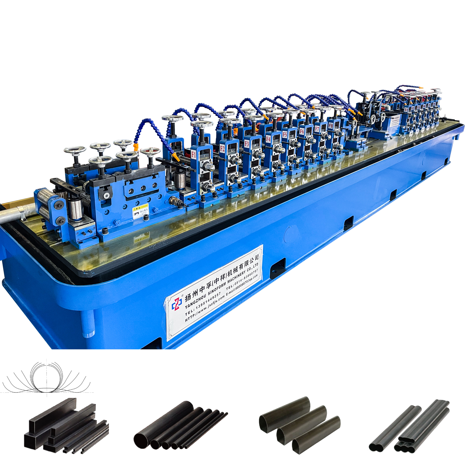
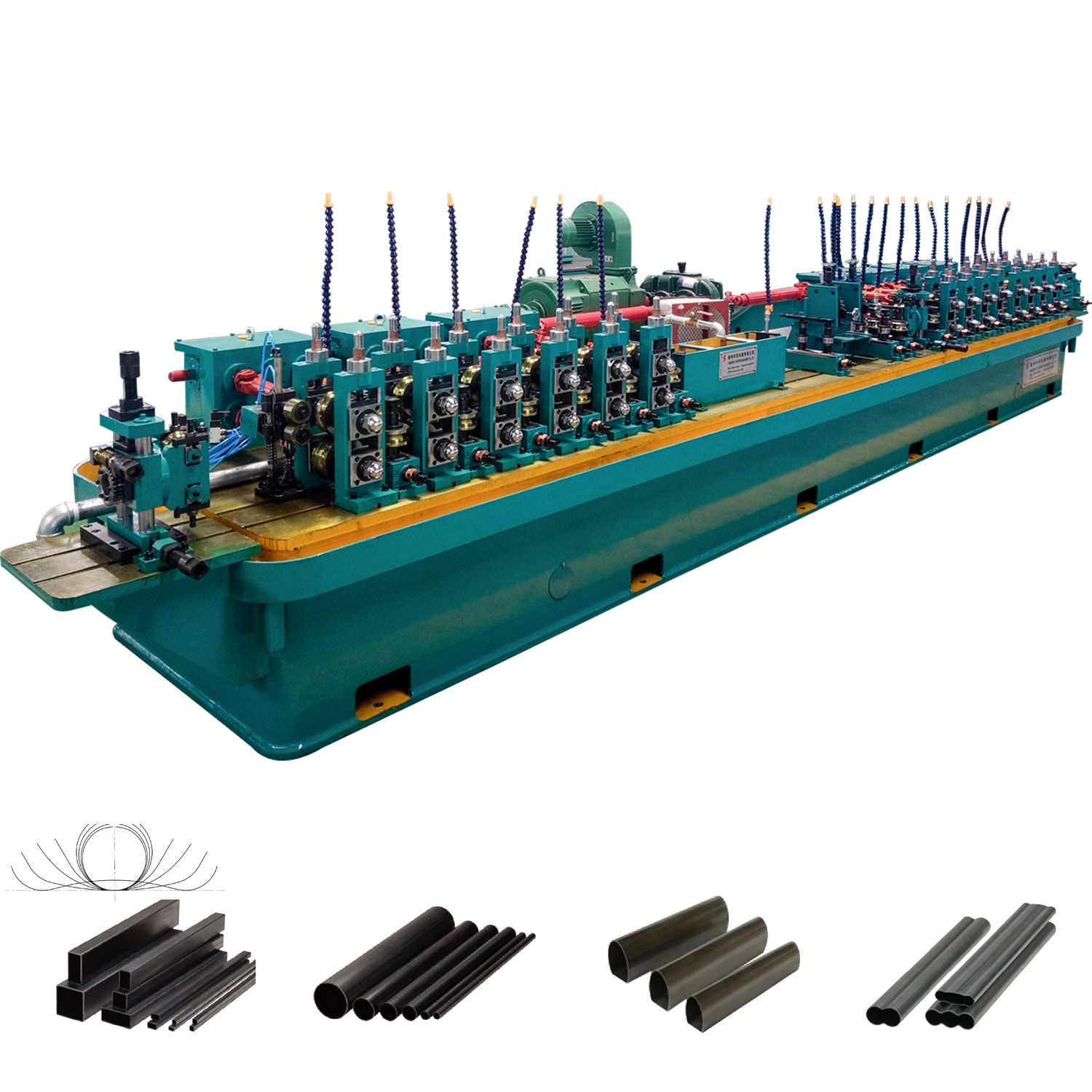
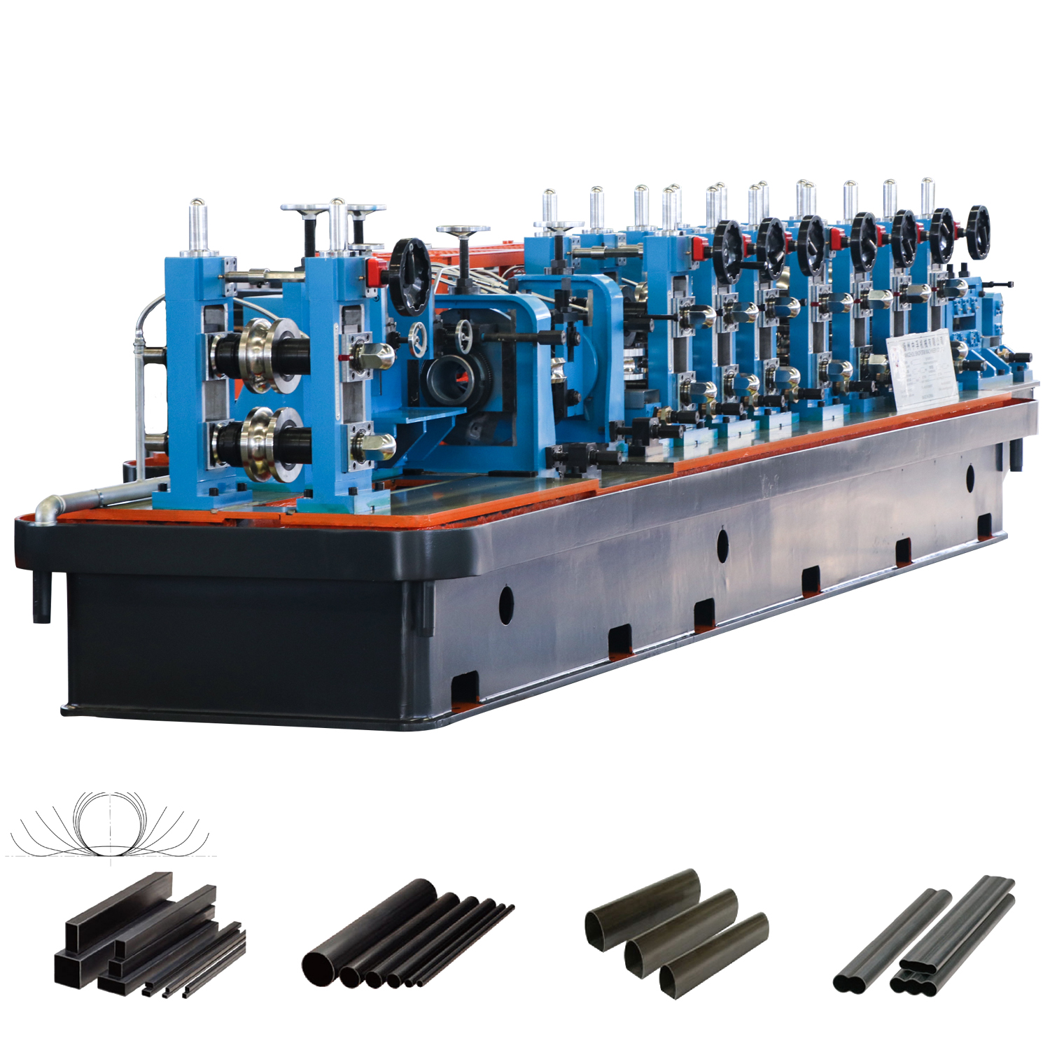
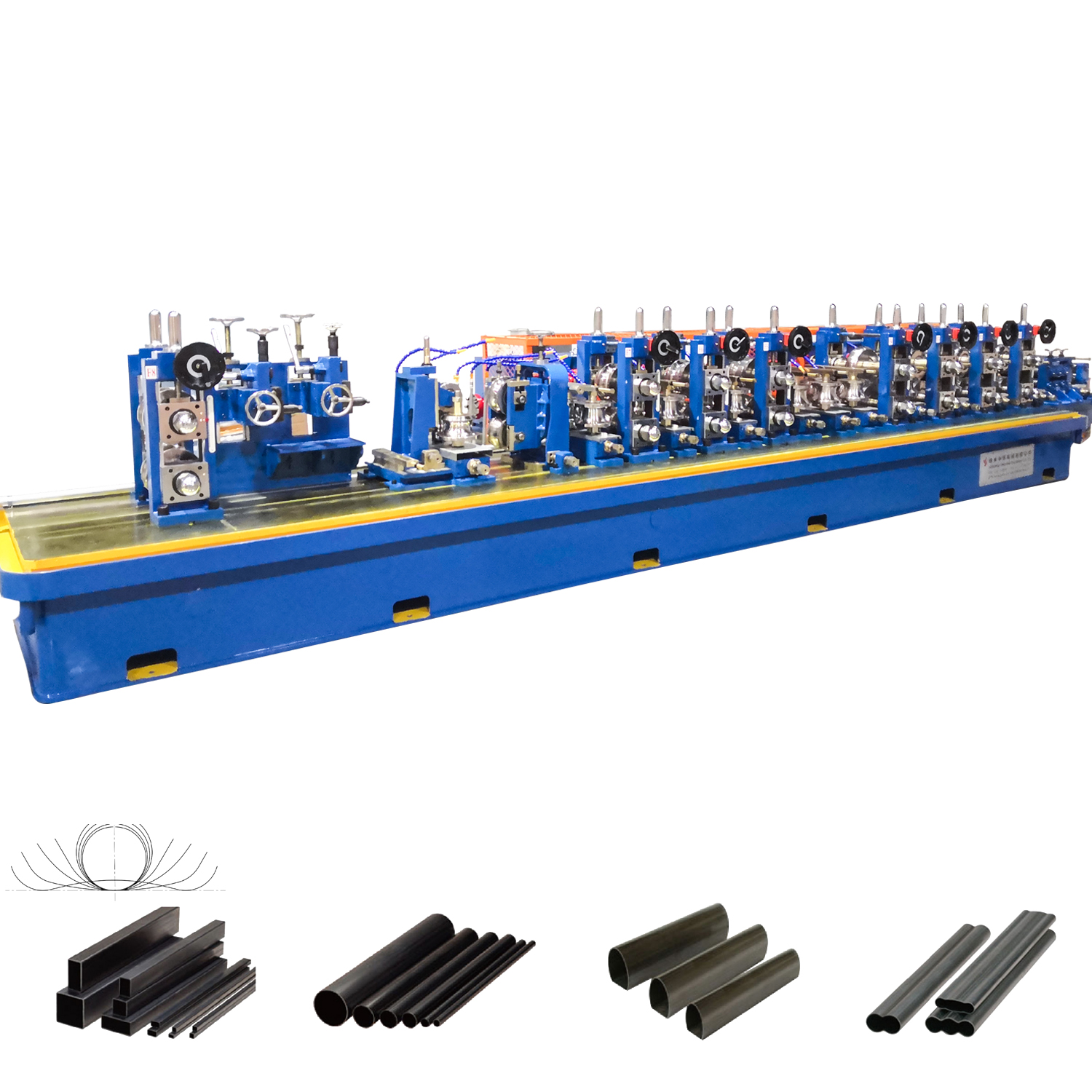
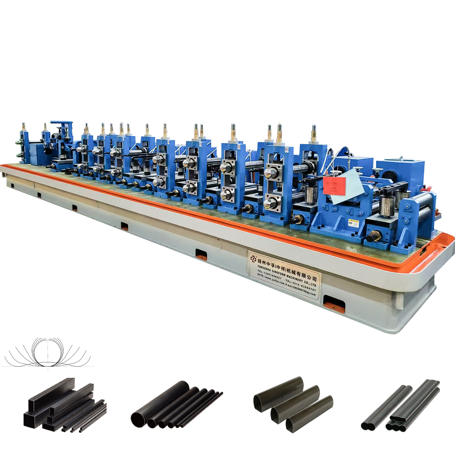
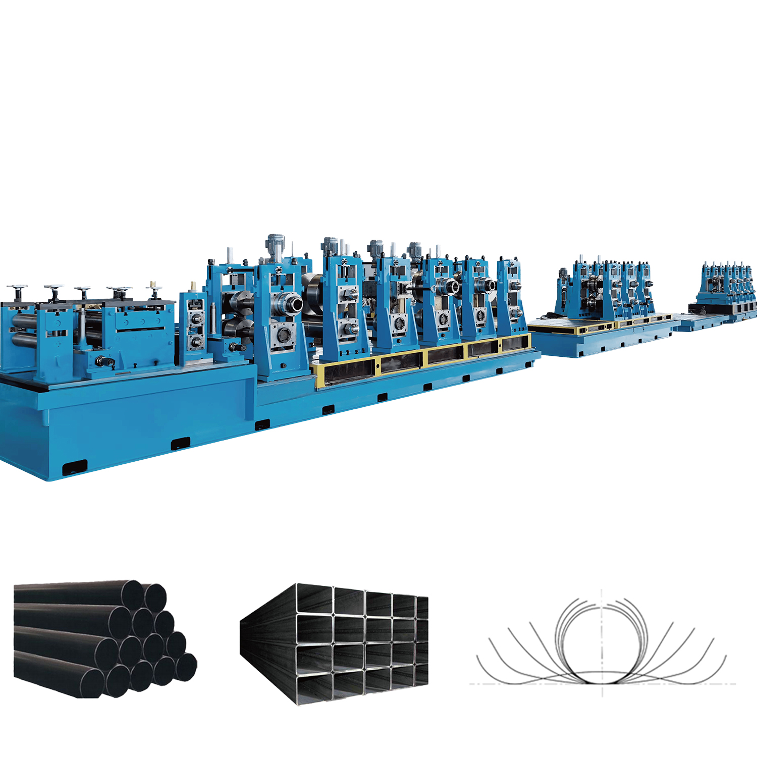
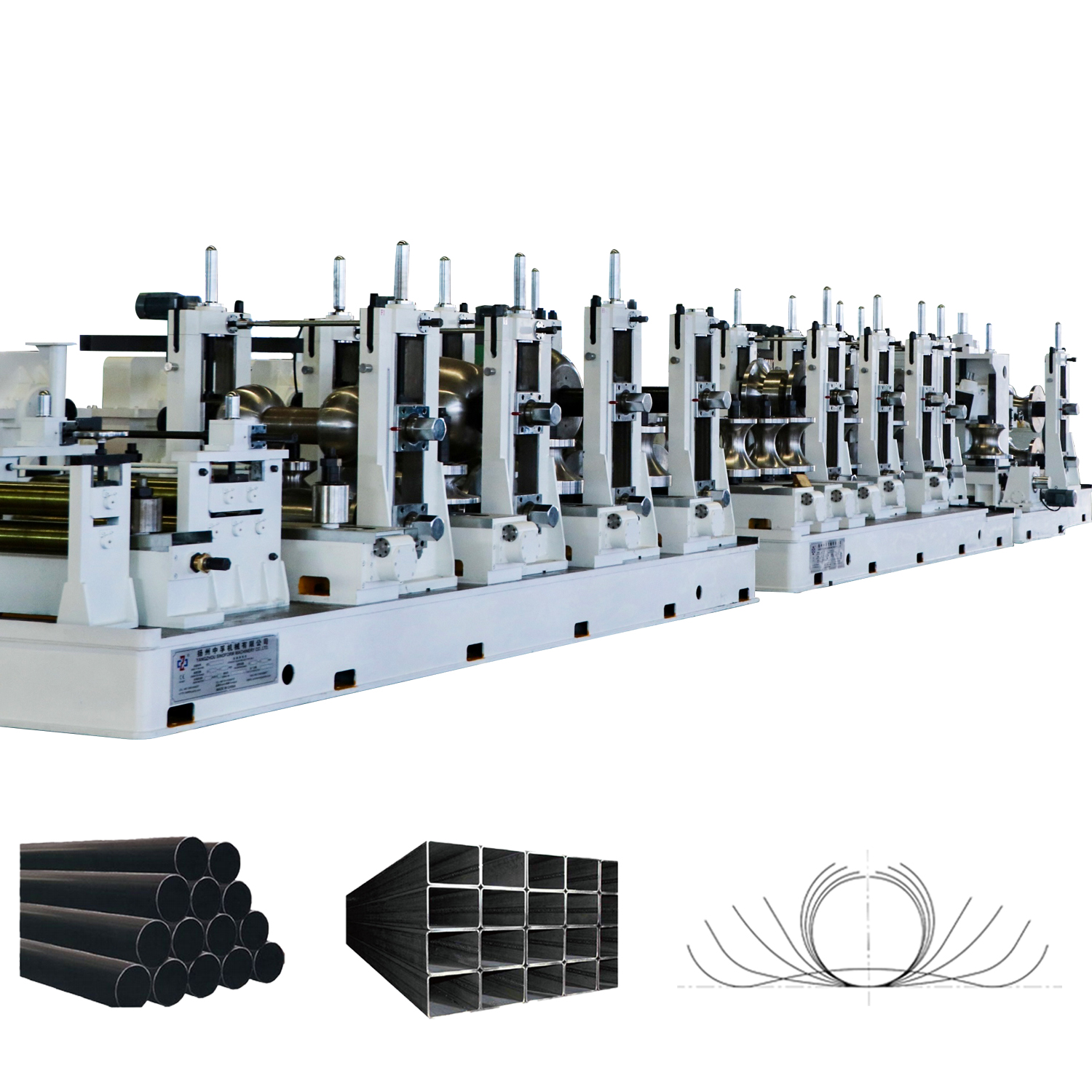
A tube mill machine operates through a series of precisely engineered rolling parts — including forming rolls, fin passes, welding squeeze rolls, sizing rolls, and straightening rolls — that progressively transform a flat steel strip into a finished welded tube or pipe. The quality, dimensional accuracy, and service life of every tube produced depends directly on the design, material grade, and maintenance condition of these tube mill rolling parts. A complete roll tooling set for a standard ERW (Electric Resistance Welding) tube mill typically consists of 40 to 120 individual roll components, depending on the tube diameter range and the number of forming stations.
The global welded tube and pipe market was valued at USD 185 billion in 2023 (Grand View Research, 2024), with electric resistance welded (ERW) and high-frequency induction (HFI) tube mills accounting for the dominant share of small-to-medium diameter production. In this fiercely competitive manufacturing environment, the rolling parts of a tube mill machine represent the highest-impact tooling investment an operator makes — a correctly specified and maintained roll set can achieve campaign lengths of 200,000–500,000 meters of tube before requiring regrinding, while an incorrectly specified set may fail within 10,000–20,000 meters while producing out-of-tolerance product.
This guide explains every major rolling part category in a tube mill machine, how each functions within the forming process, what materials they are made from, how they wear, and how to specify them correctly for different tube dimensions and material grades. Whether you are a mill operator, a tooling engineer, or a procurement specialist, this is the definitive technical reference for tube mill roll components.
Content
- 1 How Does a Tube Mill Machine Work? The Rolling Process Overview
- 2 What Are the Main Rolling Parts of a Tube Mill Machine?
- 3 Which Roll Materials Last Longest? A Comparison of Tube Mill Roll Tool Steel Grades
- 4 Why Roll Tooling Specification Determines Tube Quality and Production Economics
- 5 How to Extend Tube Mill Roll Life: Maintenance and Regrinding Best Practices
- 6 Frequently Asked Questions About Tube Mill Machine Rolling Parts
- 7 Conclusion: Getting Tube Mill Rolling Parts Right Is a Production Economics Decision
How Does a Tube Mill Machine Work? The Rolling Process Overview
A tube mill machine converts a continuous steel strip into a welded circular tube through a sequential rolling and welding process — each station of rolling parts performing a specific deformation task that cumulatively transforms flat strip into a precise cylindrical profile.
The complete process sequence in a standard ERW tube mill follows these stages:
- Strip entry and edge conditioning: The steel strip enters from a coil, passes through an accumulator, and receives edge preparation (milling or shaving) to ensure consistent weld edge geometry.
- Breakdown rolling (forming section): A series of horizontal and vertical roll stands progressively bend the strip edges downward, beginning the forming of the U-shape cross section. This is where the breakdown rolls perform their critical initial forming work.
- Fin pass rolling: Fin passes continue the forming process, guiding the strip into a near-circular profile while keeping the edges elevated and aligned for welding. The fin height precisely controls the open seam geometry entering the weld zone.
- Weld squeeze pass: Squeeze rolls apply controlled inward pressure at the weld point, upsetting the heated, plasticized strip edges together to form a forge-welded seam under high-frequency electrical heating.
- Sizing section: After welding, the welded tube passes through multiple sizing stands that reduce the outer diameter to the final specified dimension and improve the roundness and straightness of the tube.
- Straightening and cutoff: Final straightening rolls correct any residual bow or camber; the flying cutoff shear cuts the continuous tube to specified lengths.
What Are the Main Rolling Parts of a Tube Mill Machine?
The rolling parts of a tube mill machine divide into seven functional categories, each engineered to perform a specific deformation function within the tube forming sequence. Understanding the role of each category is essential for correct tooling specification, setup, and maintenance.
1. Breakdown Rolls (Forming Rolls)
Breakdown rolls are the first active forming components a strip encounters after the entry section — they perform the initial bending work that transforms flat strip into a progressively deepening U-shape, and their profile design determines the strain distribution across the strip width through the entire forming section.
- Function: Each breakdown stand typically consists of a top horizontal roll with a convex or multi-radius forming profile and a bottom horizontal roll, with side rolls (vertical rolls or edge rolls) to guide the strip edges and prevent edge flaring.
- Number of stands: Typically 4–8 breakdown stands depending on tube diameter, strip thickness, and material grade. High-strength steel (HSS) and stainless applications may require additional stands to limit per-stand strain.
- Profile design: Top roll profile follows a multi-radius curve designed using incremental bending theory — the standard Karman or Westergren forming schedules are the basis for most modern roll design software. The forming radius at each stand progressively decreases toward the tube radius.
- Material: Tool steel (typically D2, Cr12MoV, or equivalent) hardened to 58–62 HRC for the forming surface. Roll bodies are heat-treated to achieve a tough core (40–45 HRC) with a hard working surface.
- Wear pattern: Breakdown rolls wear primarily at the transition radii and at the contact line with the strip edge — areas experiencing the highest contact stress and relative sliding. Wear typically manifests as surface roughening and radius distortion that degrades surface finish and dimensional accuracy of the formed tube.
2. Fin Pass Rolls
Fin pass rolls are the most technically critical rolling parts in a tube mill machine — they complete the forming of the tube cross-section from U-shape to near-circle while simultaneously orienting and controlling the weld edges to achieve the correct angle of convergence, edge height uniformity, and strip tension entering the weld zone.
- The fin: The defining feature of a fin pass roll is the projecting fin on the top (upper) roll that fits into the open seam of the near-circular strip, keeping the edges separated and at a controlled height while the lower roll supports the tube OD. The fin height and angle directly control the V-angle (included angle between the two strip edges) entering the weld point — typically 4–7 degrees for HFW (High Frequency Welding) mills.
- Number of stands: Typically 2–4 fin pass stands. The final fin pass stand (closest to the weld box) is the most critical — its fin geometry has the most direct influence on weld quality.
- Fin wear criticality: The fin tip is the most wear-sensitive surface in the entire roll set. A worn fin tip with excessive radius or width will allow the strip edges to come together at a lower height (reduced V-angle), reducing heat penetration uniformity and causing weld defects including cold welds and hook cracks. Fin pass roll sets are typically reground when fin tip wear exceeds 0.1–0.15 mm on the tip radius.
- Material: High alloy tool steel (H13, SKD61 or equivalent for the upper fin roll) or high-speed steel (M2, SKH51) for extended campaign life in abrasive applications. Carbide-tipped fin inserts are available for stainless and high-chrome steel applications.
3. Weld Squeeze Rolls (Pressure Rolls)
Weld squeeze rolls apply controlled radial inward pressure at the weld point to forge the two heated strip edges together, achieving the metallurgical bonding that forms the welded seam — their profile and position are critical to weld integrity.
- Configuration: Standard 2-roll squeeze boxes use a top and bottom roll. Advanced 3-roll configurations (top, left-45°, right-45°) provide more uniform radial pressure distribution around the tube circumference, reducing the ovality introduced by the squeeze force. Some high-speed mills use 4-roll or cage roll designs.
- Squeeze amount: The upset (reduction in outer circumference at the weld point) must be sufficient to expel the molten weld flash and forge solid metal together. Typically 0.5–3% of the tube outer circumference depending on wall thickness and material. Insufficient upset causes cold welds; excessive upset causes wall thinning and excess flash that can jam the ID bead removal tool.
- Material and surface: Squeeze rolls are typically made from alloy tool steel (D2 or equivalent) with a ground and polished bore to minimize surface marking on the tube OD at the weld zone. Chrome or TiN coating is applied in some applications to reduce friction and surface adhesion.
- Wear mode: Grooving wear at the centerline contact point is the primary failure mode, caused by concentrated contact stress at the weld upset point. A grooved squeeze roll transfers groove geometry onto the tube OD at the weld seam, causing surface marking defects that typically trigger rejection.
4. Sizing Rolls
Sizing rolls reduce the welded tube's outer diameter to the specified final dimension through controlled cold reduction, simultaneously improving roundness, straightness, and surface finish after the dimensional distortions introduced by the welding and weld bead removal operations.
- Number of stands: Typically 4–8 sizing stands. Each stand applies a small incremental reduction — typically 0.5–2.5% OD reduction per stand. Total sizing reduction across all stands is typically 5–15% of the formed OD entering the sizing section.
- Configuration: Alternating horizontal (2-roll) and vertical (2-roll) stands are the traditional configuration, achieving near-uniform circumferential strain. Modern high-precision mills use 4-roll sizing stands at each pass, which provide superior roundness and eliminate the ovality that alternating 2-roll passes can introduce.
- Diameter tolerance: Properly maintained sizing rolls in a well-set mill achieve OD tolerances of ±0.1–0.2 mm on tube diameters up to 100 mm, meeting EN 10219, ASTM A500, and ISO 657 structural hollow section standards.
- Roll bore profile: The bore profile must be precisely machined to a radius slightly larger than the tube radius (typically radius = tube OD/2 + 0.02–0.05 mm) to account for elastic springback after the roll pass. Under-radius bores cause flat spots; over-radius bores result in undersized tube OD.
5. Turk's Head (Combination) Rolls
Turk's head rolls are 4-roll combination stands where all four rolls act simultaneously on the tube OD — two horizontal and two at 45 or 90 degrees — providing true 4-point contact forming that achieves superior roundness compared to 2-roll stands. They are used as both intermediate sizing stations and final finishing passes in precision tube mills.
- Primary advantage: True radial forming from four directions simultaneously eliminates the sequential ovality introduced by alternating 2-roll stands, achieving roundness tolerances of 0.05–0.15% of OD on precision tube production.
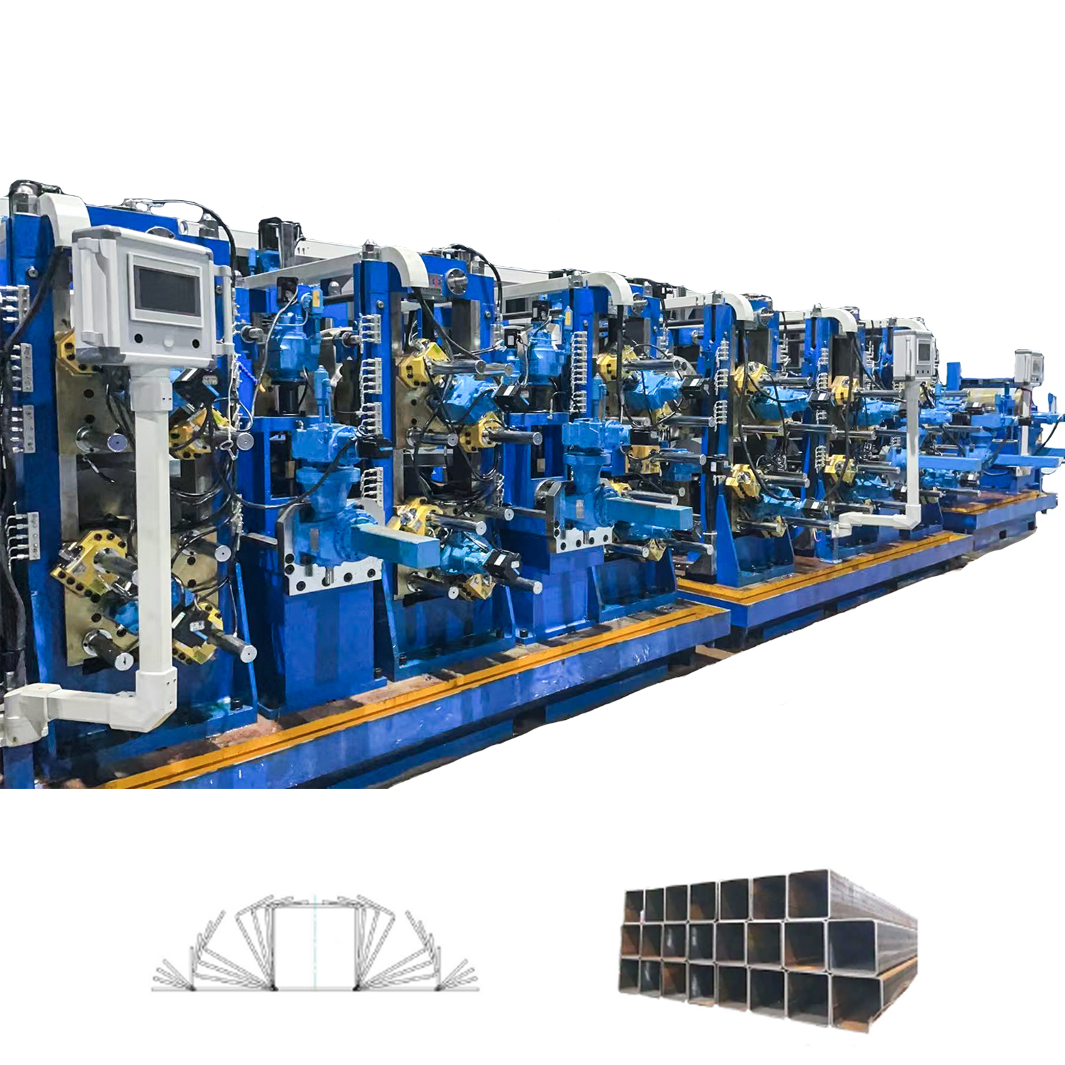
- Typical application: Square and rectangular hollow section (SHS/RHS) tube production uses turk's head rolls as the square-forming station, where the four-sided simultaneous contact is essential for achieving sharp corner radii and flat face geometry.
- Adjustability: High-end turk's head stands feature independent roll adjustment in multiple axes, allowing the mill operator to fine-tune roll gap and roll alignment without removing the roll set — reducing changeover downtime significantly.
6. Straightening Rolls
Straightening rolls remove residual bow and twist from the finished tube by applying controlled bending in alternating planes, causing yielding and stress redistribution that leaves the tube in a stress-balanced, straight condition.
- Types used in tube mills: In-line straighteners with 2–5 pairs of offset rolls are the most common configuration. The offset (how far the center roll is displaced from the pass line) determines the degree of bending and the residual stress state of the straightened tube.
- Straightness standards: Properly straightened structural tube achieves straightness within 0.2% of length (2 mm per 1,000 mm) per EN 10219. Precision mechanical tube can achieve 0.05% of length with appropriate straightener roll settings and roll condition.
- Roll profile: Straightening rolls have a concave bore matched to the tube OD, ensuring full-width contact without edge bite that would mark or damage the tube surface. Roll surface finish is critical — roughness above Ra 0.8 µm transfers surface texture to the tube and causes friction-induced tube rotation that degrades straightness achievement.
7. Guide Rolls (Edge Rolls and Turret Rolls)
Guide rolls — including vertical edge rolls between forming stands, turret-mounted guide assemblies, and roll guide blocks — control the lateral position, twist, and edge height of the strip throughout the forming section without applying primary forming forces. Although they do not directly shape the tube, their alignment critically influences strip tracking, edge weld preparation, and the uniformity of forming strain across the strip width. Misaligned guide rolls are responsible for a disproportionate share of edge wave defects, twist, and off-center welds encountered in tube mill production.
Which Roll Materials Last Longest? A Comparison of Tube Mill Roll Tool Steel Grades
The material grade selected for each tube mill rolling part determines campaign length, regrind frequency, and total tooling cost per meter of tube produced. The table below compares the most widely used roll material grades across key performance parameters.
| Material Grade | Hardness (HRC) | Wear Resistance | Toughness | Best Application | Relative Cost |
| Cr12MoV (D2 equivalent) | 58–62 | High | Medium | Breakdown and sizing rolls; general carbon steel tube | Low |
| H13 (SKD61) | 48–52 | Medium | High | Fin pass upper rolls; high-impact forming applications | Low–Medium |
| M2 / SKH51 (HSS) | 62–65 | Very High | Medium–Low | Fin passes; sizing rolls for HSS and stainless tube | Medium |
| PM-HSS (Powder Metallurgy) | 64–67 | Superior | Good | High-speed precision mills; stainless and duplex tube | High |
| Tungsten Carbide (WC-Co) | 72–80 (HRA) | Highest | Low (brittle) | Fin inserts; squeeze roll inserts; copper and aluminum tube | Very High |
| Ductile Cast Iron (SG Iron) | 40–50 | Medium–Low | Very High | Straightening rolls; large-diameter backup rolls | Very Low |
Table 1: Comparison of roll material grades used in tube mill machines by hardness, wear resistance, toughness, and application suitability. HRC = Rockwell C hardness; HRA = Rockwell A hardness (used for carbide).
Why Roll Tooling Specification Determines Tube Quality and Production Economics
The specification of tube mill machine rolling parts is the single highest-impact technical decision in tube production economics — correctly specified rolls running on the right mill at the right production speed can produce 300,000–500,000 meters before regrinding, while poorly specified rolls may degrade surface quality, dimensional tolerance, or weld integrity within the first 20,000–50,000 meters of production.
Key Specification Parameters for Tube Mill Rolls
| Parameter | Specification Detail | Impact if Wrong |
| Roll bore radius (forming profile) | Must match tube OD ±0.02 mm after springback correction | Ovality; diameter out-of-tolerance; surface marking |
| Fin tip geometry (height and angle) | Controls V-angle at weld point (typically 4–7°) | Weld defects; cold welds; hook cracks; penetrators |
| Roll face width | Must clear tube OD at both edges without edge bite | Edge marking; burrs; surface defects at tube OD edge |
| Roll bore (shaft fit) | Interference fit H7/k6 or H7/m6 per application | Fretting; roll slip; shaft damage; position repeatability loss |
| Surface roughness (Ra) | Ra 0.2–0.4 µm on forming surfaces after final grind | Transfer of roll surface texture to tube OD; increased friction |
| Roll hardness uniformity | Maximum ±2 HRC variation across roll width | Uneven wear; premature profile distortion; tube dimension variation |
Table 2: Critical specification parameters for tube mill machine rolling parts, their technical requirements, and the production consequences of incorrect specification.
How to Extend Tube Mill Roll Life: Maintenance and Regrinding Best Practices
Proper maintenance and timely regrinding of tube mill rolling parts is the most cost-effective way to reduce tooling cost per meter of tube produced — a roll that is reground at the correct time retains 80–90% of its regrind allowance (total metal available for regrinding before the roll becomes undersized), whereas a roll run until catastrophic wear failure may retain only 40–60% of this allowance.
- Lubrication: Apply a suitable water-based coolant or cutting fluid to all forming roll contact surfaces during production. This reduces friction-induced heat generation, lowers the coefficient of friction from typically 0.15–0.25 (dry) to 0.05–0.10 (lubricated), reduces adhesive wear, and carries away fine metal debris that acts as an abrasive in dry rolling. Coolant flow rate should maintain forming zone temperature below 60°C as measured by contact thermometer or thermal camera.
- Regrind trigger criteria: Establish measurable regrind trigger criteria rather than relying on subjective observation. Typical criteria: OD variation on output tube exceeds 50% of the specified tolerance; tube surface roughness Ra increases above 1.6 µm; weld defect rate increases above the established control limit; fin tip wear measured optically exceeds 0.10–0.15 mm.
- Regrind process: Use CNC roll grinding machines with CBN (cubic boron nitride) wheels for hardened tool steel rolls above 60 HRC. The grinding arc should match the original profile within ±0.01 mm. Always verify the reground profile using a profile projector or CMM before returning rolls to service. Stock reground rolls should be stored vertically to prevent bore distortion.
- Roll change frequency as a KPI: Track roll life in meters of tube produced per kilogram of roll weight as a normalizing KPI across different tube sizes. Industry benchmark for carbon steel ERW tube on Cr12MoV rolls is 80,000–150,000 m/kg for forming rolls and 40,000–80,000 m/kg for fin pass rolls, depending on tube OD and wall thickness.
- Storage and handling: Store roll sets in dedicated roll racks in a climate-controlled room (temperature and humidity control prevents corrosion on ground surfaces). Apply rust preventative oil before storage. Mark each roll with its regrind count — rolls that have been reground to within 2–3 mm of minimum diameter should be flagged for upcoming retirement rather than regrinding again.
Frequently Asked Questions About Tube Mill Machine Rolling Parts
Q: How many roll sets does a tube mill typically require for a product change?
A complete tube mill roll change for a new tube diameter requires replacing all forming, fin pass, squeeze, and sizing rolls — typically 40–120 individual roll components depending on mill size and number of stands. Modern tube mills are designed for quick-change roll cassette systems where entire stand assemblies are pre-set offline and swapped as a unit, reducing changeover time from 6–8 hours (individual roll change) to 2–3 hours (cassette change). Mills producing a limited size range typically keep 2–3 complete roll sets per size in inventory to ensure one set is always available while another is being reground.
Q: What causes roll marking on the tube OD surface?
Roll marking — the transfer of roll surface features (scratches, grooves, corrosion pitting) to the tube OD — has four primary causes: (1) a damaged roll surface from a previous production problem (strip edge bite, foreign metal inclusion); (2) roll surface corrosion from inadequate rust prevention on stored rolls; (3) excessive forming pressure causing adhesive wear and pickup of tube material onto the roll surface; (4) insufficient coolant, causing thermal softening of the roll surface. The remedy depends on cause: reground rolls eliminate surface damage; proper storage eliminates corrosion; reduced roll gap or adjusted forming schedule addresses excessive pressure; improved coolant delivery addresses thermal issues.
Q: What is the difference between ERW tube mill rolls and HFW tube mill rolls?
ERW (Electric Resistance Welding) and HFW (High Frequency Welding) are the same fundamental process — HFW is the modern term for the same process using high-frequency (typically 150–450 kHz) current. The tube mill rolling parts for both are functionally identical in most respects. The distinction appears primarily in the fin pass and squeeze roll design: HFW mills operating at high speeds (40–120 m/min) on thin-wall tube require tighter fin geometry tolerances (V-angle control to ±0.5° versus ±1° on slower mills) and squeeze roll profiles optimized for the higher weld upset speed. Roll materials for HFW mills more commonly specify high-speed steel or PM-HSS grades versus tool steel for lower-speed ERW production.
Q: Can the same roll set be used for different wall thicknesses of the same OD?
Yes, with limitations. Sizing and straightening rolls are largely insensitive to wall thickness variation for the same OD — the tube OD is what contacts the roll bore, and wall thickness variation has minimal effect on the sizing geometry. However, fin pass rolls and breakdown rolls are sensitive to wall thickness because the strip width (which determines the forming circumference) changes with wall thickness at the same OD. A single forming roll set typically accommodates a wall thickness range of approximately ±20% of the nominal design wall before the fin engagement and edge roll positions require adjustment beyond normal range. Beyond this range, dedicated roll sets for each wall thickness are needed.
Q: How do I identify which rolling part is causing dimensional defects in my tube?
Systematic defect isolation in a tube mill follows a process of elimination working backward from the finished tube. OD oversize or undersize that persists across multiple coils points to sizing roll wear or incorrect gap setting. Ovality (non-round cross-section) points to incorrect squeeze roll gap or worn sizing rolls with non-uniform bore profiles. Diameter variation that follows a periodic pattern (spike every N meters) points to an eccentric or damaged roll causing a repeating mark — identify which roll has the defect by measuring the circumference corresponding to the repetition period and matching it to roll circumferences in the mill. Weld-area surface defects (raised seam, depressed seam, marking at 6 and 12 o'clock positions) point to squeeze roll groove wear or squeeze roll gap setting issues.
Q: What is the typical cost of a complete roll set for a medium-diameter tube mill?
Roll tooling cost varies significantly with tube OD range, roll material grade, and the number of stands in the mill. As a general benchmark, a complete tube mill roll set in Cr12MoV / D2 tool steel for a medium-sized mill producing 25–60 mm OD tube typically costs USD 15,000–35,000 for forming, fin pass, squeeze, and sizing rolls combined. High-speed steel (M2/SKH51) roll sets for the same mill cost approximately 2–3x more at USD 30,000–80,000 but deliver campaign lives 1.5–2.5x longer, often resulting in lower cost per meter of tube produced. Premium PM-HSS and carbide insert roll sets for high-speed or stainless tube mills can cost USD 80,000–150,000 for a complete set.
Conclusion: Getting Tube Mill Rolling Parts Right Is a Production Economics Decision
The rolling parts of a tube mill machine — from the initial breakdown rolls to the final straightening rolls — collectively represent the most technically demanding and highest-impact tooling system in tube and pipe manufacturing. Each roll family has a specific function in the progressive forming sequence, a specific failure mode to monitor, and a specific material specification that optimizes campaign length for the production environment.
The fundamental principle is that tube mill roll tooling cost is not the purchase price — it is the cost per meter of acceptable tube produced. A roll set costing twice as much but delivering 2.5 times the campaign life before regrinding reduces tooling cost per meter by 20% while also reducing changeover frequency, changeover labor cost, and the risk of production-quality incidents during setup after roll changes. This total cost of ownership framework should guide every tube mill roll specification decision.
For mill operators establishing or upgrading their roll tooling programs, the recommended starting point is a comprehensive audit of current roll life data (meters per regrind, regrind intervals, defect root causes attributed to roll condition) — this data typically reveals 2–3 specific improvements in roll specification or maintenance practice that together can reduce total tooling cost per meter by 15–35% without requiring capital equipment investment.